• Please note that Audiokarma will be offline briefly for updates early on Monday morning, September 28th.

Potted Ouput Transformer- Is it PP or SE UL ??

Trypower

Member
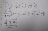
If I had an unknown overseas (to the west of CA) POTTED output transformer in my hands with 3 primary leads and a 0-4-8 secondary, how would I know for certain if it was push pull or single ended with a UL tap? This particular transformer is claimed to be UL single ended. I attached a file showing what measurements I made. So, without wiring it into an amplifier and looking at scope patterns or some sort of distortion analyzer, what measurements would tell me for certain it's truly wound to be SE?

I'm quite aware you can use a PP output single ended with great success. Witness Eric Barbour's "Single Ended Glory for Under $100" from Glass Audio magazine circa 1995 using the Sansui 1000A 7591 PP outputs- ignoring the center tap- for running a #45 single ended. Those were Hashimoto sourced, pretty sure 6.6K primary into 8 and 16 ohm secondary. I've done this and I can tell you firsthand you will end up with a remarkable sounding 2 watts of that single ended Glory. And scope patterns will affirm this works very well indeed.

What I'm NOT familiar with is a SE UL output. I'm a TRIODE person all he way, whether it be SE or PP. So I never thought about this 1st paragraph. Remember it's potted, so the laminations can't be seen as a telltale. Measurements were made with a digital LCR meter and quality multimeter. Can anyone shed any light?
 

Attachments

  • IMG_20240401_182222913.jpg
    IMG_20240401_182222913.jpg
    50.7 KB · Views: 47
Register to hide this ad
With a primary inductance of only 14.7 H I would guess this is a well-gapped transformer, so an SE. And with the even spread of resistances as well as inductance across the primary ”middle tap” I would guess the UL ratio is 45-50%.

My 2 cents.
 
Last edited:
I would apply a signal between the CT and one end, then see if the other end is exactly the same amplitude. This won't differentiate between PP and 50% UL, but if it's different than the applied voltage, it rules out PP.

Jack
 
I'd put a small, maybe 6v, ac power supply on the full secondary and see what each side of the center tap reads. If it's the same voltage from each side to the center tap, fair bet it's a push pull transformer. A single ended transformer with a screen tap will have very different voltages on each tap. Be careful as 6v on the secondary could still generate hundreds of volts on the primary. Consider hooking up your measurement equipment with the unit unplugged then plugging it in to get the measurement, and disconnecting it to switch taps...
Be very careful.
Also. I don't personally refer to single ended transformers as "ultralinear" because David hafler and Herb Keroes only really developed push pull amplifiers. They most likely would not considered single ended "high fidelity" and likewise wouldn't have touched it with a ten foot pole. Applying their trade name to something they would not have had anything to do with seems sacrilegious to me.
 
@trobbins - the measurements page shows with and without the 100 ohm resistor. That 100 ohm resistor was soldered and shrink wrapped on that tap by the manufacturer of the amplifier. I undid the shrink wrap so to measure without that resistor. It's an EL34 single ended UL stereo amplifier from overseas. The square wave pattern is terrible at 100 hertz and 10Khz. Minor ringing at 1Khz that's quickly damped. Removing the "UL" tap and connecting the EL34 in triode makes for a much better "picture". I understand that many other variables are in play. I'm just highly suspicious of the output trans which caused me to wonder how to prove out "what" it is.

As far as UL, no, not for me. It all gets connected triode SE or triode PP- unless it's a guitar amp ...

In days past I would have had a basement full of everything and anything including a PP mid grade transformer to compare, I don't now, so ... The DCR measurements either end to "UL" or "CT" are close enough it could be PP. The primary inductance is likely also close enough to a low-fair-mid grade PP output.

'll have to try the 6vac experiment and voltage applied to primary experiments, might be a few days. Thanks.
 
if it was in a single ended amp, its probably a single ended transformer. Push-pull transformers work very poorly in single ended applications.
 
50% UL ratio is not uncommon; in fact it's optimum for some tubes. 100 Ohm screen resistor makes sense, 100 Ohms at the center-tap of a P-P transformer does not. This plus the relatively low inductance point to a single-ended design. Connect a variable DC supply to the primary and measure secondary inductance vs. current - when it begins to drop quickly, you've reached saturation. That will be a very small current for a P-P transformer.
 
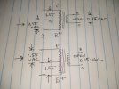
Here's the results of a couple of experiments suggested. The 100 ohm resistor is ignored, it's not part of the question, I'm just looking for a way to determine if the transformer itself is a PP transformer enlisted to do SE duty. Thanks to all for the input.
 

Attachments

  • IMG_20240403_172025725.jpg
    IMG_20240403_172025725.jpg
    76.5 KB · Views: 13
The first measurement indicates 3k3 for PP (end to end) with 8R secondary, and that the primary half-windings are the same for turns.

I note you said the secondary was 0-4-8R. How was that determined?

Normally when measuring turns ratio, Vac would be applied to secondary as already done, to confirm the primary half windings are actually the same, which they are. Then one of the primary half-windings would be 'driven' by the signal generator, and the unloaded voltage on the other half-winding would be compared to the unloaded secondary winding voltage - as that avoids uncertainty from winding resistances. A sinewave is used for that testing, to avoid any voltage measurement inaccuracy with meters.
 
@trobbins - Thank you. I just now applied a 1.55vac since wave across the B+ lead and "CT / UL" and see the same 1.55vac from "CT / UL" to plate lead. Just to confirm I also did the same but across the Plate lead to "CT / UL", results being the same measuring to B+ lead. The unloaded 8 ohm secondary shows 0.15vac.

As far as 0-4-8 I'm just believing the amp manufacturer. It's likely correct as the primary impedance works out to be what a SE EL34 would prefer.. My newer Fluke doesn't have a low ohms scale (unfortunately) so I used a different meter and see 0.5 ohms and 0.8 ohms across the secondaries.
 
Did you find a suitable book/article to do the calculations of impedance yourself from those results ?

I find it practical to use 6.3V or 12Vac from a transformer, as the 0.15Vac is starting to get low in resolution from your meter. You can also measure the 4 ohm tap to confirm that value if you were concerned.
 
I use an isolation transformer and a variac, aiming for 1 volt across the full secondary. It gets out of that fuzzy resolution zone but still gives me enough decimals for accuracy.
 
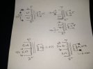
I re-ran some of those tests with my BK bench generator, I was lazy the first time and used a handheld at 1Khz. All compares favorably to the previous tests for relationship. As an example: 7.13 volts 100 hz sine wave into the 8 ohm secondary produced 143.2 volts on the full primary, evenly split at 71.3 vac to the UL/CT (??). Then 7.32vac into the primary splits evenly at 3.68 and 3.66 to that ?? tap.

As far as primary impedance I used a digital LCR meter at 100hz as mentioned in the first post. Saves me the forgotten formulas. This showed 3.4K which would be in the appropriate range, so no concerns there.

Attached for more, all at 100hz. Thanks for the input !
 

Attachments

  • IMG_20240405_232311434.jpg
    IMG_20240405_232311434.jpg
    62.6 KB · Views: 10
Last edited:
Can you clarify what Vac is measured across 8R-com secondary winding, and ??-com secondary, and also the 8R-?? winding, where ?? is the anticipated 4R tap, and 'com' is the end of that winding?
 
Back
Top Bottom