

You are using an out of date browser. It may not display this or other websites correctly.
You should upgrade or use an alternative browser.
You should upgrade or use an alternative browser.
Potted Ouput Transformer- Is it PP or SE UL ??
- Thread starter Trypower
- Start date


A LCR meter can't measure the operating impedance of a transformer. It can only measure the characteristic inductance of various windings. That's not the same thing.As far as primary impedance I used a digital LCR meter at 100hz as mentioned in the first post. Saves me the forgotten formulas. This showed 3.4K which would be in the appropriate range, so no concerns there.
Jack

Trypower
Member
I'd respectfully disagree. True Z readout at a number of different frequencies. I've owned a couple thru the years, they're essentially right on the money testing known transformers. Speakers too for that matter. I'll post up a few photos tomorrow or so, just got done keeping up with F1 Japan qualifying, VERY late here. Thanks.
Trypower
Member
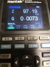
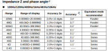
Here's a couple of images of the LCR meter. One is of the meter connected to the full primary into an 8 ohm load resistor. Just as a backup I also connected it to the wide open amplifier 100K pot. Also attached is a partial photo from the on line owner'manual regarding partial Z measurement. I forgot to photo the 4 ohm tap measured into a 4 ohm load, it reads 3.54K.
This impedance changes with frequency, just as a speaker would do the same. I don't know what all goes into measurements when a transformer manufacturer rates their primary impedance as a singular number. Clearly it's not all static under operation and I understand your reference to operating impedance.
Admittedly haven't used this meter much, it's a fairly new acquisition, maybe a year ago, as I ended up selling everything and anything to do with hi-fi some 5-6 years ago. Then had a loss of mind and momentarily got reinterested- for a few months. The previous meter was a BK or Tenma that I punished for years. Once again, measuring known specs it was always true to those. In the early days I remember using a signal generator and a pot of somewhat larger than expected impedance, then a multimeter to somehow equalize voltages across ??, "ring" the transformer somehow and then measure the pot. Can't remember now how that was accomplished, but it too worked perfectly- and no additional expense. Looked for that "trick" on the net some long time now and couldn't find it so ...
This impedance changes with frequency, just as a speaker would do the same. I don't know what all goes into measurements when a transformer manufacturer rates their primary impedance as a singular number. Clearly it's not all static under operation and I understand your reference to operating impedance.
Admittedly haven't used this meter much, it's a fairly new acquisition, maybe a year ago, as I ended up selling everything and anything to do with hi-fi some 5-6 years ago. Then had a loss of mind and momentarily got reinterested- for a few months. The previous meter was a BK or Tenma that I punished for years. Once again, measuring known specs it was always true to those. In the early days I remember using a signal generator and a pot of somewhat larger than expected impedance, then a multimeter to somehow equalize voltages across ??, "ring" the transformer somehow and then measure the pot. Can't remember now how that was accomplished, but it too worked perfectly- and no additional expense. Looked for that "trick" on the net some long time now and couldn't find it so ...
Attachments

Last edited:
Well, that's a different beast. Not too long ago, that would have been referred to as a Z-meter. The standard LCR meters I'm familiar with don't have that functionality. Considering this model can read impedance and phase angle with the secondary of a transformer loaded, it should indeed provide something closely resembling operating impedance. The last machine I used with that capability was an RF VNA that cost hundreds of times as much. 
Jack
Jack
As an afterthought, I wonder if that could be used to help settle the old argument that surfaces here from time to time. It's said by some that measuring a transformer's voltage ratio with the secondary open, and then converting to the impedance ratio, creates the number specified by the manufacturer. Others (including myself) contend that the voltage ratio must be measured with the secondary terminated into the appropriate load resistance. It would certainly be interesting to measure 10 or 20 known output transformers with a meter of that type, just to see how well it agrees with manufacturers' ratings.
Jack
Jack
Trypower
Member
In my previous life I would have had those 10-20 transformers around to measure with this particular meter and be able to answer that question. The only transformer this meter has measured is the one I question. But I'm pretty confident. I'd rather wish for something BK so service if needed I wouldn't worry. Not that I should, this company has been around since 1999 apparently and makes other forms of test equipment like oscilloscopes and waveform generators, etc. I haven't attempted to do an online update of the meter, we all know how updates can go wrong. Not sure if my Chromebooks can do that and our Microsoft desktop is getting older. So if it's not broke best not to "fix" it.

Transformer inductance also changes with signal level, increasing at low frequencies up to the point of saturation, so low-frequency response could be better than a low-level measurement would indicate. And DC current also affects inductance, though this effect is reduced by gapping the core. Even push-pull transformers may have a small effective gap if the E and I laminations are inserted in blocks rather than alternating them. PA amp and organ transformers were often made this way to reduce the effect of mismatched output tubes (and it reduced manufacturing labor!).
For Jack's question, I think manufacturers tended to use the unloaded impedance ratio of the primary to full secondary (rounded off to the nearest 100 or 1000). This is known (they counted the turns) and easily measured with precision. They could have even used the impedance they were shooting for when they started the design, which ended up better with a slightly different ratio since filling all layers give the best coupling. Secondary taps are seldom in the exact 4/8/16 ratio, and even if they were, winding resistance may not be, resulting in slightly different loaded impedance for each tap. Here are the Dynaco transformers I have tested, all on 8 Ohm tap, would not be the same on 4 or 16 Ohms.
For Jack's question, I think manufacturers tended to use the unloaded impedance ratio of the primary to full secondary (rounded off to the nearest 100 or 1000). This is known (they counted the turns) and easily measured with precision. They could have even used the impedance they were shooting for when they started the design, which ended up better with a slightly different ratio since filling all layers give the best coupling. Secondary taps are seldom in the exact 4/8/16 ratio, and even if they were, winding resistance may not be, resulting in slightly different loaded impedance for each tap. Here are the Dynaco transformers I have tested, all on 8 Ohm tap, would not be the same on 4 or 16 Ohms.
Attachments

Last edited:
I just want point out that counting turns produces the turns ratio, not the impedance ratio. The result fails to account for the DCR of the windings and other losses necessary to determining impedance. If manufacturers are doing this, they're doing it wrong, and the output tubes won't see the specified impedance.I think manufacturers tended to use the unloaded impedance ratio of the primary to full secondary (rounded off to the nearest 100 or 1000). This is known (they counted the turns) and easily measured with precision.
Jack
Trypower
Member
Looks like Triode store still offers that Z-565. That is one really good output transformer. I'm familiar with it from days gone by.
I have an experiment in mind. This is a stereo amplifier. The outut tubes are being run way cool. Call it 320V PL to K (one output tube only running), ~ 20 V across a 500 ohm resistor- so 40ma. The PT is inadequate to do much about that. What if I disconnected the existing choke, looks to be 150ma sizing, and ran the output in question as a choke, and then just used the other output for a complete single channel circuit. One drawback is the difference in DCR. But otherwise the output as a choke would/should easily handle what would not exceed 75ma total current draw one channel. So if I did this what might I be seeing or testing/looking for as a clue to the original question of is it PP or true air gapped SE? Don't know why this is bugging me, curiosity just has a firm grip ...
About the meter I'm using- I added a chart attachment of everything the meter can "see" regarding the output and the choke. The output numbers are unloaded secondary. Maybe an EE or much more experienced tech guy that me can gather something from this. I can't, at this point now it's too many new tricks for the old dog to joggle around.
I have an experiment in mind. This is a stereo amplifier. The outut tubes are being run way cool. Call it 320V PL to K (one output tube only running), ~ 20 V across a 500 ohm resistor- so 40ma. The PT is inadequate to do much about that. What if I disconnected the existing choke, looks to be 150ma sizing, and ran the output in question as a choke, and then just used the other output for a complete single channel circuit. One drawback is the difference in DCR. But otherwise the output as a choke would/should easily handle what would not exceed 75ma total current draw one channel. So if I did this what might I be seeing or testing/looking for as a clue to the original question of is it PP or true air gapped SE? Don't know why this is bugging me, curiosity just has a firm grip ...
About the meter I'm using- I added a chart attachment of everything the meter can "see" regarding the output and the choke. The output numbers are unloaded secondary. Maybe an EE or much more experienced tech guy that me can gather something from this. I can't, at this point now it's too many new tricks for the old dog to joggle around.
Attachments

Last edited:
is it PP or true air gapped SE?
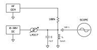
It's easy to tell them apart if you look at the difference in inductance when DC current is varied. I use the method below. Gapped inductors will change only a little when current in increased, as opposed to un-gapped, which exhibit a large and noticeable difference.
Jack
Trypower
Member
Jack, Thanks for that. Question though- Is the "measurement" a scope picture? Would something like this be appropriate-
https://www.amazon.com/Adjustable-Voltage-Regulator-Digital-Display/dp/B07PPNZ3ZJ/ref=asc_df_B07PPNZ3ZJ/?tag=hyprod-20&linkCode=df0&hvadid=507792222889&hvpos=&hvnetw=g&hvrand=4588433409451580917&hvpone=&hvptwo=&hvqmt=&hvdev=c&hvdvcmdl=&hvlocint=&hvlocphy=9005892&hvtargid=pla-825263996296&psc=1&mcid=2cc6268857cc3fc5b9460309a3f6839a&gclid=Cj0KCQjwq86wBhDiARIsAJhuphnQUugX8ELUv737HMsLJz5Vn1U68xLKD-JGukNE8RHjb4bb5WiWwvQaAimWEALw_wcB
Sorry for long link, didn't shorten as anticipated
https://www.amazon.com/Adjustable-Voltage-Regulator-Digital-Display/dp/B07PPNZ3ZJ/ref=asc_df_B07PPNZ3ZJ/?tag=hyprod-20&linkCode=df0&hvadid=507792222889&hvpos=&hvnetw=g&hvrand=4588433409451580917&hvpone=&hvptwo=&hvqmt=&hvdev=c&hvdvcmdl=&hvlocint=&hvlocphy=9005892&hvtargid=pla-825263996296&psc=1&mcid=2cc6268857cc3fc5b9460309a3f6839a&gclid=Cj0KCQjwq86wBhDiARIsAJhuphnQUugX8ELUv737HMsLJz5Vn1U68xLKD-JGukNE8RHjb4bb5WiWwvQaAimWEALw_wcB
Sorry for long link, didn't shorten as anticipated
Last edited:
Here's how it works:
The inductor under test is paralleled with a known value capacitor to create a resonant circuit. Sweeping the generator back and forth by hand, the amplitude of the signal seen on the scope will peak at the LC resonant frequency. The value of the inductor can then be calculated based on the known value of C and the frequency.
To measure the inductance when DC is flowing, the CCS is adjusted for the desired current. A milliammeter inserted between the DC voltage source and the CCS can be used to monitor current. For a given current flow, the DC supply voltage should be adjusted just above the point where the sine wave distorts. This creates the minimal voltage drop (headroom) across the LM317 necessary for it to operate, and prevents excessive dissipation in the part.
For your purpose, it's not so important to know the exact value of inductance. You're looking for changes when DC current is varied. I would start by making a measurement with about 10mA to 30mA flowing, then increase to about 100mA. This will cause the resonant frequency to shift, and the new frequency represents the change in inductance. A gapped inductor like a high quality plate choke will show relatively little change.
For best accuracy in measuring the actual inductance, the capacitor must be sufficiently large to swamp the parasitic capacitance of the CCS and inductor under test. Values around 1uF are suitable.
Jack
The inductor under test is paralleled with a known value capacitor to create a resonant circuit. Sweeping the generator back and forth by hand, the amplitude of the signal seen on the scope will peak at the LC resonant frequency. The value of the inductor can then be calculated based on the known value of C and the frequency.
To measure the inductance when DC is flowing, the CCS is adjusted for the desired current. A milliammeter inserted between the DC voltage source and the CCS can be used to monitor current. For a given current flow, the DC supply voltage should be adjusted just above the point where the sine wave distorts. This creates the minimal voltage drop (headroom) across the LM317 necessary for it to operate, and prevents excessive dissipation in the part.
For your purpose, it's not so important to know the exact value of inductance. You're looking for changes when DC current is varied. I would start by making a measurement with about 10mA to 30mA flowing, then increase to about 100mA. This will cause the resonant frequency to shift, and the new frequency represents the change in inductance. A gapped inductor like a high quality plate choke will show relatively little change.
For best accuracy in measuring the actual inductance, the capacitor must be sufficiently large to swamp the parasitic capacitance of the CCS and inductor under test. Values around 1uF are suitable.
Jack
Last edited:
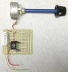
This is the jig I use for the CCS. It's essentially a LM317 (TO-220 case) on a small heatsink. I use a 50Ω WW pot for adjustment. The range is roughly 25mA to 300mA. The upper end will sometimes be limited by the DC resistance of the inductor if it requires more than the maximum DC available from the supply.
I use the Micronta supply below (22-121), because it has a low noise floor that comes in handy for other purposes. I connect the outputs in series when needed to provide a 0-30V range. There are lots of options for all of this.

Jack
I use the Micronta supply below (22-121), because it has a low noise floor that comes in handy for other purposes. I connect the outputs in series when needed to provide a 0-30V range. There are lots of options for all of this.
Jack
Last edited:
Trypower
Member
Jack, most appreciative of that information and explanation. Thank you. Not sure I can tackle that anymore. Age definitely has caught up. I never did have a bench top DC variable supply, and the Variac left with everything else. And the 50 and 100ohm WW pots for hum balance are gone too. Not familiar with the LM317 either. But I'll let that soak in for a while and see if I'm up to the task. I might just go ahead with my little experiment in the meantime as just a couple of undone solder joints and some jumper leads is all I need to do. Well this after I figure out why the 30 year old Mustang won't start ....
Trypower
Member
@gadget73 - Well it doesn't have spark, so ... Just put a cap and rotor on it, could have been orig at 68K mi. 94 Cobra ultra clean. We know all 8 plug wires and plugs didn't go at the same time. 40+ pounds of cranking fuel pressure. I did pull the coil wire before the first start this year to bring the oil pressure up. Hope that didn't hurt anything. Started and ran fine for a few days. Now, not a hint. Stock air cleaner box is a PITA to remove, TFI buried under there I think?

TFI or PIP would be my guess then. PIP is in the distributor, far more annoying to replace than a TFI. If you have +12v to the coil and no spark there isn't too much else it can be.
I think 94 they re-located it off the distributor but I don't quite know where they hid it. Somewhere up by the rad support I think, maybe over by the battery? Not as familiar with the SN95 stuff under the hood. Mine have all been Fox or Panther cars. Next time I need a rack on the Mark VII I might consider an SN95 rack swap though. The Fox ones kinda suck and most of them are so worn out that even the rebuilds drive badly.
I think 94 they re-located it off the distributor but I don't quite know where they hid it. Somewhere up by the rad support I think, maybe over by the battery? Not as familiar with the SN95 stuff under the hood. Mine have all been Fox or Panther cars. Next time I need a rack on the Mark VII I might consider an SN95 rack swap though. The Fox ones kinda suck and most of them are so worn out that even the rebuilds drive badly.
My '08 Triumph (motorcycle) ran fine until I parked it for two years. Then it wouldn't start, so I spent hours cleaning dried, crusty ethanol gunk out of the carbs. Still nothing, although it would catch and burp with ether. Took the carbs off the motor and soaked and cleaned them two more times before finally replacing the ignition control unit. That was it. It had failed while the bike was just sitting in the garage. Surprised I didn't burn up the starter troubleshooting that one. 
Jack
Jack