• The move to the new server is done. There are some software and database maintenance updates in process. This has us passing the hat around to help out. We appreciate any donations. Seriously, even a dollar helps. The payment page may be found here - https://www.audiokarma.org/support.html

Potted Ouput Transformer- Is it PP or SE UL ??

For your purpose, it's not so important to know the exact value of inductance. You're looking for changes when DC current is varied. I would start by making a measurement with about 10mA to 30mA flowing, then increase to about 100mA. This will cause the resonant frequency to shift, and the new frequency represents the change in inductance.
This is a simple test setup that many can arrange, as they may have a scope and a sig gen. The measurement looks at the change in the incremental inductance as the dc operating point on the BH curve of the inductor is shifted further away from the origin and towards the knee (substantial slope change) as the core heads into its saturation region. Perhaps worth noting that the signal swing across the choke is quite small, and likely far below the circa 5-10Vrms of a CLC smoothing choke, and far far below the swing of a choke-input filter choke which is perhaps more like the OPT application here could get to. Larger signal swings will change the incremental inductance, to a level that is more representative of what a datasheet may represent for a choke or OPT (as they are typically measurement at 5-20Vrms) - the likely inductance increase is 30-60% at say 50-100Vrms compared to 1Vrms, and there may be a noticible increase from the small signal applied in this test to say 1Vrms. This inductance increase with signal swing is then countered by an inductance decrease due to DC current. I measured a 25% decrease in full primary inductance at 12Vac when a PP 15W hi-fi OPT was subjected to 8mA dc imbalance - which is just output stage valve bias mismatch and nothing like SE operation, which is certainly an indicator of whether the OPT was intended for SE operation, and worth looking for here where the topic is to assess if an OPT was or is capable of SE operation, or was likely just designed for PP operation.

For a 10H choke, and the indicated 1uF resonant cap, the test frequency would be around 50Hz, which as indicated should be sufficiently below the 1-10kHz region where the choke's inductance and its internal shunt capacitance likely resonate (and I'd anticipate an OPT part would also be in the same range).
 
This method has proven to be very reliable. I tested a batch of swinging chokes a few years ago and was amazed how close the readings were to the specs. The chokes were rated 6H/35mA and 3H/70mA. I measured slightly more than 6H at 0mA (CCS disconnected), 6H/35mA, 3H/70mA and 2H/100mA. :)

Jack
 
@gadget73 - Sent you a PM (I think I did that right). Got it started, but...

@TriodeLuvr - Sold my Honda 350cc 4 cylinder back in 72 or 73 (yes, I'm old) after some idiot ran a stop sign and nearly killed me. Never rode it again.
 
Last edited:
Pretty sure you fellows are going to lose me. But I'll try and hang in there. I've been known to de-pot transformers just for those nice covers and house something different underneath. For example, all those Heath W3,4,5 power transformers are sketchy. Nice big flanged cans, but the PT inside is about 1/3 the size. No wonder they go south. Between wives (yes, important), I heated up the oven and placed a couple of bricks under the flanges. Don't remember how long it took (a few hours I think), but out slid the potting material with the transformer. Cleanly no less! A little sanding, etching primer, hammertone black and house a proper transformer. ** Disclaimer, worked for me, not fire department recommended or EPA clean air standards approved. WAF would be a big fat -0- ** Maybe a propane torch outside would be better ...

For this amp I won't, it wouldn't be worth the effort or cost. And the chassis is stainless, not drilling into that for new transformer mounting holes.

Speaking of etching primers, I'm reminded ... I used this stuff for years back then, works great. When I sold off all that "stuff" years ago I just left the cans sit on the shelves. Well, some years later I went down to the basement and noted a layer of haze and a certain paint like odor. Looked around, couldn't see anything obvious as the cause. Took me a couple of days to figure that it was a can of etching primer that ate thru the can itself and was slightly leaking. If you have any of those around best to use them up within a reasonable time or just get rid of them. They etched the container !! I guess they would.
 
It's not just etching primers. I've seen spray lubricants that were stained black after being in the can for a few years. Anything sprayed with that stuff would have been contaminated. Best to always check older products in aerosol cans before use.

Jack
 
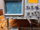
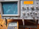
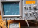
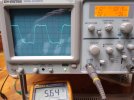
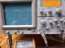
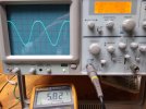
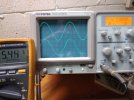
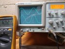
So here's what I did today. Desoldered a couple of points and with a couple of jumper leads I swapped in one of the outputs substituting for the choke, and ran the signal into the other channel output stage. Aside from losing 1/4 watt due to the ~10Vdc loss because of the 100 ohm higher resistance of the output trans (now choke) I really don't see any significant change in the waveforms. The amp is triode connected. It's down on power as the PT says that's all I got.

You can see the "hitch" in the upper half of the 100Hz sine wave, it's always there, changing the power tube or biasing of the power tube doesn't offer any improvement. The waveforms presented to the output tube are clean. The front end is 1/2 12AU7 with a BK 4003 ahead of that. At 8 ohm tap- Slight ringing at 1K, damped pretty quickly. 10K square isn't so "special". 100Hz square .... I used to seeing a 45 do way better with a good quality transformer.

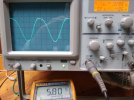
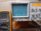
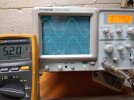
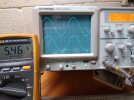
I'll load the photos in order, hopefully they'll stay that way. Should be100Hz sine, square; 1Khz sine, square; 10Khz sine, square with (unused) output as choke. Then same with existing choke back into circuit. The volt meter (vac) is across an 8 ohm load. You can also see the frequency in the digital display of the scope. The sine waves are at the limit of distortion. The square waves are just adjusted to be at the same voltage as the sine wave.

Decided to load 2nd group separately, with existing choke in circuit. All in all seems to have passed the single ended test??
 

Attachments

  • IMG_20240411_180123252.jpg
    IMG_20240411_180123252.jpg
    97.8 KB · Views: 8
  • IMG_20240411_180311220.jpg
    IMG_20240411_180311220.jpg
    95.7 KB · Views: 8
  • IMG_20240411_180405865.jpg
    IMG_20240411_180405865.jpg
    104.9 KB · Views: 8
  • IMG_20240411_180451924.jpg
    IMG_20240411_180451924.jpg
    96.2 KB · Views: 8
  • IMG_20240411_180612143.jpg
    IMG_20240411_180612143.jpg
    91.7 KB · Views: 6
  • IMG_20240411_180824727.jpg
    IMG_20240411_180824727.jpg
    95.2 KB · Views: 8
Last edited:
Next group

EDIT- This group can end up out of order. Don't know why. It was correct, then it wasn't when I looked at it later. I posted them up one at a time to make sure this couldn't happen, but it did ... So I posted up an edit note listing the new order. But now at the moment it's back in the proper order. You may have to look at the scope readout paying attention to the decimal to be sure.
 

Attachments

  • IMG_20240411_182622546.jpg
    IMG_20240411_182622546.jpg
    100.2 KB · Views: 6
  • IMG_20240411_182526951.jpg
    IMG_20240411_182526951.jpg
    91.5 KB · Views: 6
  • IMG_20240411_182357590.jpg
    IMG_20240411_182357590.jpg
    90.9 KB · Views: 6
  • IMG_20240411_182305803.jpg
    IMG_20240411_182305803.jpg
    94.7 KB · Views: 3
  • IMG_20240411_182216994.jpg
    IMG_20240411_182216994.jpg
    91.1 KB · Views: 3
  • IMG_20240411_182129711.jpg
    IMG_20240411_182129711.jpg
    99.4 KB · Views: 3
Last edited:
Those asymmetrical sines all represent relatively high even-order distortion. Are you sure this isn't drawing grid current?

Jack
 
It could very well be pushed slightly harder by a 1/4 watt or so. I've been down that road looking at any grid voltage at the same time. No appreciable difference in the waveform that I remember, but tomorrow (or the next day) I'll have another look. Glad you brought that up. Developed a slight water drip over my workbench with all the rain and was in a hurry up mode. Had to use a towel over the outlet strip.
 
I was thinking also possibly the driver stage isn't biased quite right. If changing the output tube bias point doesn't move that at all, it makes me think the problem is earlier. Especially if the grid looks the same as the speaker side.
 
I have looked at the driver. Input at the EL34 grid is right on except for slight rolloff using 10Khz square wave. Until onset of drawing grid voltage that is. I'll try and add some more photos soon, assuming my workbench survives all this rain !!

Edited, for 10Khz square wave (not 100hz)
 
Last edited:
NOTE- the second group may or may not be in the order I put them in. I loaded them one at a time to avoid this from happening. For at least some period of time they changed order. See Edit note post #48

At this moment, 12:52AM ET April 12, 2024 both orders are correct. Haven't deleted and reposted any photos. Beats me.
 
I decided to give this another baseline, I'll add this post and then another later. The choke is wired back in the circuit where it belongs as is the output I had previously repurposed as a choke. Both channels are operating, one is wired triode, the other is wired UL so to compare (again). The amp of course has lost a little power with the additional current draw of two channels. With a GZ34 the PT is only good for about 300 EL34 plate volts- both channels- with a 500 ohm (each) cathode resistor. I'll add a measurement later, but close enough. The scope photos are taken at the limit of drawing a DC grid voltage on the grid of the EL34 output tube.

I see where the photos in post #48 are now out of order again. I'll again load these new photos in order 100-1K-10K, but name them this time since I don't know in what order they'll end up. Tomorrow I'll add the UL channel. This will all lead up to a new question which I'll ask after you see that channel.

The top trace in each photo is the EL34 (in triode) grid, lower trace is output into 8 ohm load resistor on 8 ohm tap. One channel is inverted. Voltmeter at output.
 

Attachments

  • EL34 Triode 10Khz square.jpg
    EL34 Triode 10Khz square.jpg
    99.9 KB · Views: 4
  • EL34 Triode 1Khz square.jpg
    EL34 Triode 1Khz square.jpg
    98.8 KB · Views: 3
  • EL34 Triode 100Hz square.jpg
    EL34 Triode 100Hz square.jpg
    99.2 KB · Views: 3
  • EL34 Triode 10Khz sine.jpg
    EL34 Triode 10Khz sine.jpg
    103.3 KB · Views: 3
  • EL34 Triode 1Khz sine.jpg
    EL34 Triode 1Khz sine.jpg
    101.3 KB · Views: 4
  • EL34 Triode 100Hz sine.jpg
    EL34 Triode 100Hz sine.jpg
    102.7 KB · Views: 4
Here's just two photos, getting a little tired of this one. Both are of the UL channel. One is a 10Khz square wave, but at the same output as the triode channel in post just above- number 54. It doesn't get any "prettier" beyond that.The other is a 1K sine wave at claimed output of 6 watts. It's worse at higher and lower frequencies. Again, EL34 grid is top trace, output bottom.

So here's my question. How is the screen tap percentage of primary winding determined for a particular tube? Is it a mathematical calculation? Is it trial and error looking at waveforms and THD? NOT a scope jockey, the proof is in what we hear, but they do tell a certain story as seen above.

Never been down the UL road in depth before. Had a couple of Dynaco 70's around previously, honestly didn't care for them. There were others. I do remember having a "Hollywood Imperial" integrated for my garage amp where I used to hang out until all hours of the morning. Was a PP EL34/6CA7 amp (might have been UL?) running into an Altec 616-8A (??) 15 in a homemade corner cab built for a 12. Enlarged the opening, ran a decent tuner and sometimes I would have to turn around and look back in amazement as to how great that sounded. Must have been the mysterious synergy that happened by chance.

But now I'm triode indoctrinated, there's no going back. Has a firm grip. If it doesn't have that midrange that can startle you it's not a great amp. For this one I'll pass it along? B+ isn't high enough, output transformers are lower end. It's actually a nice looking amp, little too much bling for me. 6L6's "look" better on the scope, sacrifices more power though. There are other possibilities for it though, we'll see. I guess since I'm in there I'll try straight pentode, just because. Last time I looked at that was years and years ago. I saw nice pointy sine waves ..... Yes, kidding.

Thanks for listening, all the input was appreciated !!
 

Attachments

  • EL34 UL 10K square.jpg
    EL34 UL 10K square.jpg
    97.8 KB · Views: 1
  • EL34 UL 1K sine.jpg
    EL34 UL 1K sine.jpg
    105.7 KB · Views: 1
I would really like to build a triode Class A push-pull amplifier. All the real triodes have become so expensive though, the thought of buying a matched set of four really makes me cringe. Plus, I don't have appropriate output transformers for such a project, only for pentodes. I'd have to really open up the wallet to do this...
 
Back
Top Bottom