• The move to the new server is done. There are some software and database maintenance updates in process. This has us passing the hat around to help out. We appreciate any donations. Seriously, even a dollar helps. The payment page may be found here - https://www.audiokarma.org/support.html

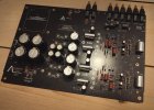
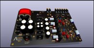
Preamplifier in progress

Thanks for the comment.

I've always liked the sound of my Acurus preamplifiers (LS11 schematic attached), and was looking for inspiration for a new project to build myself when I stumbled on a thread about a year ago on another forum about the 90's elektor preamp (second attached schematic, original Elektor artikel), that to my liking had many similarities to the Acurus that I like so much.
There is not much to be found online regarding the Elektro preamplifier, but those who heard it described the preamp as highly regarded, some even write it as one of Top-5 best preamps they ever heard, and that was enough for me to give it a go:)

I've done several proto builds based on the Elektor schematic with my tweeks described in post#1, only mono versions, with and without DC-servo, and the servo version proved to be much more stable, so that's what did my end drawing from there on out to the final layout posted here in this thread.

Best regards
 

Attachments

Last edited:
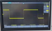
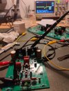
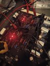
Two pictures from the protobuild.
-A 10kHz square wave, captured on the first protobuild, July 16, 2024.
-The second picture: I'm testing the final proto, November 27, 2024. Sorry for the mess on the table;)
 

Attachments

  • 1000006043.jpg
    1000006043.jpg
    67.6 KB · Views: 40
  • 1000005514.jpg
    1000005514.jpg
    137.2 KB · Views: 40
Two pictures from the protobuild.
-A 10kHz square wave, captured on the first protobuild, July 16, 2024.
-The second picture: I'm testing the final proto, November 27, 2024. Sorry for the mess on the table;)
Thank you! Looking forward your updates.

I have similar plan: To eventually build my own system, but cannot do it now, because my life is too "dynamic"...:).

In a mean time I am using every precious moment to study the problems audio systems present and possible ways to tackle them. Besides Douglas Self's books, I am also using Bob Cordell's "Designing Audio Power Amplifiers".

Best

Soundork
 
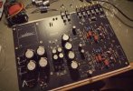
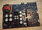
Just throwing another picture of progress, its getting late here and next step is matching transistors, so I'll might proceed tomorrow or Sunday with the build.
I should have stopped after installing resistors and start matching, but couldn't resist trying some of the footprints to check fitment and went on soldering some other areas. It's really no problem, just have to be a little more careful when moving the PCB around while working on it.
Everything fits like a charm so far and I'm very very pleased:)
1000006132.jpg
Best regards
 
Last edited:
1000006140.jpg
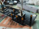
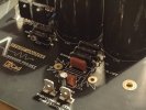
I've ordered power resistors for the PSU about 4 days ago. They will arrive tuesday, untill then I cannot proceed due to the positioning of the heatsinks, so I'm stuck for now. But it's getting close to some pre-tests!:)

Also, I've ordered a second value of BIAS-potentiometers. The proto-builds were tested with a 10Kohm pot to BIAS, but a 5Kohm might do better with the TO126 transistors at the outputs. This will be tested in my proto-build before installing the value I decide to go with in the final build. We'll see.....

I haven't bought the volume pot yet, but the PCB is drawn to house a 10K DACT CT-2 stepped attenuator, which is the last missing part in my inventory.

Best regards
 
Regarding the Mills MRA05 resistors, I found an old order from 2019 where I purchased 16x MRA05: it said 3.15€ pr resistor, today it's easily 10€ pr MRA05 in Europe. Wow...$$$!
In US they a cheaper..

Hifi collective and Banzai Music still have Elna Silmic ll RFS and Nichicon LKG/UES/UKZ, but they're not cheap, and stock is getting low on most attractive values.

The overall project here is hopelessly "audiophool" in many ways, I know.
I have got used to source what Mouser have in stock for my builds (and it's definitely alot cheaper!), but I saw the opportunity to build this one final all-in preamplifier, with all my old favourite parts one last time.
The parts might be impossible to find next year, so :)

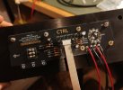
Also, I tested the frontpanel control last evening, and it performed as intended. All relays worked and current draw was right on target. I did a short video attached to the link https://photos.app.goo.gl/HGMazXFzAXAWCKDP7

In the video the three diodes in the bottom of the frontpanel is channel 1-3.
The top right LED is MUTE, and the top left LED is OUTPUT RELAY ENGAGED.
I added the output relays with a timer (a simple R-C time constant) just to be sure that the DC-servo has some time to settle if needed to avoid pops. The timer functions only at power up and and after mute is disabled.

Best regards
 
Last edited:
Outstanding soldering!! It warms my Mil-spec-trained heart to see it.

This is an extremely cool endeavor and I hope is sounds 1/10th as good as it looks.
 
Outstanding soldering!! It warms my Mil-spec-trained heart to see it.

This is an extremely cool endeavor and I hope is sounds 1/10th as good as it looks.
Thank you very much for the comment.

The main PCB is 2mm thick so the soldering required a bit more attention and patience then the standard 1.6mm PCB's out there. I use Kester Series44 63/37 leaded solder, and normally I work without adding extra flux. In this case the added flux just made good soldering a tad easier.

I still need to power up the emitter/follower section before I'll connect the full preamp to live AC.
I've bought some 680ohm/25watt resistors to load the PSU and establish if the voltage is in the ballpark around ±15VDC. I need roughly 45-46mA pr preamp-stage, and the 680ohm is close enough for this test.
Fingers crossed this stage will work equally well so I can start drilling the mountingholes in the chassis. We'll see :)

Best regards
 
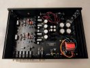
Sharing another photo, mocking up the chassis with a test installation of the PCB's to check that all my measurements lined up. And they did :)
All drillings of the buttomplate has ended with success and the PCB fitted without the need to enlarge some of the homemade drill holes! ;) Super!
I'll show the drillings and how I decided to do the faceplate mountings later on as this might be of interest to others.

IMG20250321215230~2.jpg

One OCD set back(!!), the control panel in the faceplate: I did make one mistake in the design process, not encountering that the Molex cable to the relays were directional, meaning that I had to rotate one of the Molex header sockets 180 degrees on one of the PCB's vs the other. This I haven't spotted, both were set same direction.... Vuups....
Everything still works as the pinout is correct in my drawings between the two boards, but the install of the Molex cable would look messy due to bends to fit with my unaccounted error in PCB layout.
I took the plunge and invest 5 minutes to correct my drawing of the faceplate PCB and invested another 45$ at JLCPCB for an "OCD-approved" solution :) I really want this to look neat and professional the best I can with the hours spend.
The PCB has been shipped today and if I'm lucky the updated control panel will arrive in the end of next week.

Best regards
 
Last edited:
A small update:
The preamp has been coneccted to live AC for the last few days. It works amazingly well with only minor adjustments. Really the only thing I've swapped was a 16V zener for 15V, and removed a 22pf mica cap at the input.
The rest have been pure fun testing! Still without sound for now..

I've ordered some new resistors for the zener's in the PSU. Currently value is 150ohm, but 42mA across the 15V zener is to hot for my liking. 270ohm would be around 23-24mA, so that's in the basket.
Voltage output is ±15.6VDC at the rails where's ±15VDC is the target, so a 270ohm wouldn't do any harm at all.
I'm really impressed with the LT4320 active bridge rectifier, voltage drop is second to none. And no hum or any audible noise from the PSU/transformer! Nothing:)

The preamp circuit is just as stable as the latest proto-builds, and I've settled with rise/fall-times of 130ns. So a decent slewrate:) With the 22pf at the input it did rais/fall of 160ns, but really there is no sign ringing or any other misbehaviour, so C3/4 is an open slot on the PCB for now.
BIAS is set to 26mA across each emitter, heatsinks is cold.
Clips in a nice and very soft manner around 9.67Vrms.
I do not have a THD-meter, but read on DIYaudio that a good preamp should measure 0.1mVAC or lower with a DMM at the outputs with the input shorted. I did this test: the proto build powered from my LabPSU with added e.caps did 0.12mVAC and the final posted here does 0.05mVAC on live AC. It doesn't tell much, but an improvement.

I'm very happy!:)

EDIT: the rais/fall-times were measured without the volume pot. The DACT CT2-10K should arrive any day now according to tracking.

Best regards
 
Last edited:
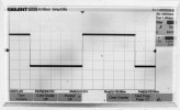
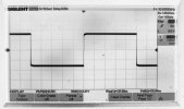
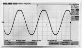
SOME MEASUREMENTS:
I've run out of 10Kohm resistors(!??), so the preamp output is loaded with a 8.2Kohm on the pictures shown:)

Input: 1Vpp @1kHz square
1000006240.jpg

Input: 1Vpp @10kHz square
1000006234.jpg

Input: 4.67Vpp @1kHz sine:
The preamp driven into clipping. Clipping starts at 9.67Vrms, here we are at 10.42Vrms. Very gentle behaviour before the flattops starts if pushed a bit further
1000006241.jpg


Best regards
 
Last edited:
Back
Top Bottom