

You are using an out of date browser. It may not display this or other websites correctly.
You should upgrade or use an alternative browser.
You should upgrade or use an alternative browser.
Preamplifier in progress
- Thread starter KNielsen
- Start date


KNielsen
Well-Known Member
Small update: I've not done much this weekend, besides from some small tests and painted the switch and knobs in a 2-component all matt black lowest gloss finish.
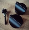
-Tomorrow the updated frontpanel PCB will arrive, with the molex connection correctly attached this time.
-Tuesday the 270ohm Mills MRA5 should arrive for the 15V zeners.
-At the end of the week a special grease for the shafts should arrive, to enhance that "torque feeling" when turning the knobs. Nyogel 767A.
Besides from that its mostly mechanical adjustments. I need to cut the shafts in correct length and other minor adjustments. Not much but pretty time-consuming to get right. There's no room for errors now
Best regards
-Tomorrow the updated frontpanel PCB will arrive, with the molex connection correctly attached this time.
-Tuesday the 270ohm Mills MRA5 should arrive for the 15V zeners.
-At the end of the week a special grease for the shafts should arrive, to enhance that "torque feeling" when turning the knobs. Nyogel 767A.
Besides from that its mostly mechanical adjustments. I need to cut the shafts in correct length and other minor adjustments. Not much but pretty time-consuming to get right. There's no room for errors now
Best regards
Last edited:
KNielsen
Well-Known Member
I've done the schematic for the PSU this evening and attached as PDF.
The preamp schematic will follow later on when I got it redrawn for possible errors on values ect..
As for the build itself, apparently I've run into holidays in the country where I've ordered some needed mechanical parts, they were shipped Friday this week.
So I'm on hold for now untill then
I have experimented with different opamps in the DC-servos while waiting.
TL071, OPA37G, OPA277PA and MUSES03's...
The servo shouldn't effect the sound (!?), and looking at the offset alone the OPA277PA is by far the best at keeping the preamp at 0mV close followed by TL071. The OPA37G doesn't work that well for some reason. I have 6 of them in my inventory, and none of the managed to keep offset below 10mV. Around 12mV out for most of them.
I've ordered the OPA277P due to slightly better tolerances then the PA-version I have, but initially the OPA277PA is more then enough to do the job.
As for the MUSES03 which costs an arm and a leg, the offset is within 3mV on both channels. I might try them in the chain when the preamp is in the living room, but doesn't expect to hear any difference with a -3dB point set to 0.15Hz on the servo.
Best regards
The preamp schematic will follow later on when I got it redrawn for possible errors on values ect..
As for the build itself, apparently I've run into holidays in the country where I've ordered some needed mechanical parts, they were shipped Friday this week.
So I'm on hold for now untill then
I have experimented with different opamps in the DC-servos while waiting.
TL071, OPA37G, OPA277PA and MUSES03's...
The servo shouldn't effect the sound (!?), and looking at the offset alone the OPA277PA is by far the best at keeping the preamp at 0mV close followed by TL071. The OPA37G doesn't work that well for some reason. I have 6 of them in my inventory, and none of the managed to keep offset below 10mV. Around 12mV out for most of them.
I've ordered the OPA277P due to slightly better tolerances then the PA-version I have, but initially the OPA277PA is more then enough to do the job.
As for the MUSES03 which costs an arm and a leg, the offset is within 3mV on both channels. I might try them in the chain when the preamp is in the living room, but doesn't expect to hear any difference with a -3dB point set to 0.15Hz on the servo.
Best regards
Attachments

Inspiring work man. Kudos!
KNielsen
Well-Known Member
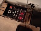
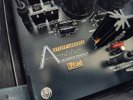
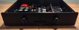
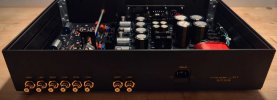
Small update: Last night I had finished enough for the first 10min of music, just before bedtime. Not nearly enough to fully test the unit without waking the kids, but the sound seems really pleasant. It's to early to judge, but did manage to play a few of my favorite tracks. Quite pleasant.
I do the last metal work this evening at my workshop so the knobs ect can be fitted and more time for a listening experience later on
Best regards
I do the last metal work this evening at my workshop so the knobs ect can be fitted and more time for a listening experience later on
Best regards
Last edited:


KNielsen
Well-Known Member
Regarding the schematic for the preamplifier.
The setup for now is running "safe", mening some of the values are set where faults should not occur at all, fingers crossed of course.
At the same time the rais/fall times has dropped a tad as posted here to roughly 130ns.
In the last proto before this end-build I easily managed below 100ns, around 90ns rail/fall was possible with 8.06ohm base resistors in the diff section and the THAT340 didn't complain at all. It does not work without base resistors should be mentioned...
I'm running 47ohm now untill I have a decent soundcard for further testing on my laptop.
Also a 22pf at the input is installed which limits the bandwidth to about -3dB @1.2MHz! It really should be enough for most listeners but; the proto was stable even in 2MHz trim, but just for now I'll keep it within reason. I didn't see any misbehaviour removing the 22pf in this unit, but kept it in place for reasons described, and a bit of common sense I guess!?!
I'm waiting for some RN55D 820ohm resistors which should arrive next week for the JFet within the CCS. I use 806ohm now as these were the only available at the time I ordered parts, but 820ohm suits the input stage much better.
The output transistors are biased to 26mA each right now, running mildly cold in my 22°C room temperature. I've run them higher and much lower in proto without issues, but want to find the ideal setting here as well. This needs further testing.
So minor adjustments, but no biggie..
The final schematic will be posted when I'm sure all values are set
Best regards
The setup for now is running "safe", mening some of the values are set where faults should not occur at all, fingers crossed of course.
At the same time the rais/fall times has dropped a tad as posted here to roughly 130ns.
In the last proto before this end-build I easily managed below 100ns, around 90ns rail/fall was possible with 8.06ohm base resistors in the diff section and the THAT340 didn't complain at all. It does not work without base resistors should be mentioned...
I'm running 47ohm now untill I have a decent soundcard for further testing on my laptop.
Also a 22pf at the input is installed which limits the bandwidth to about -3dB @1.2MHz! It really should be enough for most listeners but; the proto was stable even in 2MHz trim, but just for now I'll keep it within reason. I didn't see any misbehaviour removing the 22pf in this unit, but kept it in place for reasons described, and a bit of common sense I guess!?!
I'm waiting for some RN55D 820ohm resistors which should arrive next week for the JFet within the CCS. I use 806ohm now as these were the only available at the time I ordered parts, but 820ohm suits the input stage much better.
The output transistors are biased to 26mA each right now, running mildly cold in my 22°C room temperature. I've run them higher and much lower in proto without issues, but want to find the ideal setting here as well. This needs further testing.
So minor adjustments, but no biggie..
The final schematic will be posted when I'm sure all values are set
Best regards
Last edited:
KNielsen
Well-Known Member
The schematic
I switched to TTA/TTC004. They just work great and better complementary pairs then A1837E/C3505E.
I've set the BIAS to 30mA (168mV across each emitter) and the temperature increase is nothing to write about.
2.2u at the input might be enough bass for most, I've set the value to 4.7u as this is what I will install in near future.
Besides from that, it just sounds sweet. And very neutral!
Best regards
//Kaare Nielsen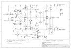
I switched to TTA/TTC004. They just work great and better complementary pairs then A1837E/C3505E.
I've set the BIAS to 30mA (168mV across each emitter) and the temperature increase is nothing to write about.
2.2u at the input might be enough bass for most, I've set the value to 4.7u as this is what I will install in near future.
Besides from that, it just sounds sweet. And very neutral!
Best regards
//Kaare Nielsen
Last edited:
KNielsen
Well-Known Member
Small udpdate:
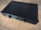
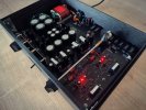
After months of listening and minor adjustments here is the final version of the schematic (also attached as hi-res PDF).
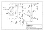
The updated schematic shows some P2P components installed on the backside of the main PCB: Rx1 which were installed to limit the BIAS current in case of open potentiometer at the BIAS circuit.
Cx1/Cx2 220nf were added right at the output transistors to tame a very minor and delicate overshoot I discovered after tons of testing. All good!
The emitters were changed to 10ohm, R34/25 got new values of 820ohm. The BIAS pot was changed to 5Kohm when Rx1 (2.74Kohm) was added. The quiescent current at the outputs is adjustable from 40mA to 86mA, and the heatsinks never gets hot to touch in either condition.
I've tried various values on the input capacitor C1, from 2.2uf and mixed values up to 6.8uf, but initially 2.2uf sounded the best, and keeping some distance to the servo cutoff by a factor of 10.
I did however improve the bass response by tweaking the servo a bit and getting the "kick" I missed by adding more current to the servo output. R13/19 are the ones that had my attention here.
Taking great care to adjust RV1 to 0mV at TP2 (servo output) after a good half hour of on-time for ambient temperatur in the preamp finishes it all, and I cannot hear the servo breath anymore, and non-existing in circuit to my ears. Excellent!
And finally, I decided to try another brand of input cap. Usually I don't believe (or try to "don't believe") in big sound changes between caps, but the Jantzen Superior-Z 2.2uf/800V really sounds neutral compared to the ClarityCap ESA 2.2uf/250V. That said, I think the sound of the ESA in this preamp will impress the most, although the details and neutrality is one level below the Superior-Z.
My opinion..
I'm measuring 0.05mVac at the outputs, so no hizz from the tweeters
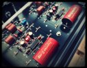
I have 4 complete set of PCB's left, and if anyone would like to give it a go I'd be willing to sell a set, including a parts list, frontpanel design files if needed ect.... Contact via PM.
-The preamp will work with either BC549C/BC559C or BC550C/BC560C.
-The frontpanel PCB doesn't have to be used, and one can easily do other control units how you like. Just as long as it's able to switch between the relays on the main PCB.
Best regards // Kaare Nielsen
After months of listening and minor adjustments here is the final version of the schematic (also attached as hi-res PDF).
The updated schematic shows some P2P components installed on the backside of the main PCB: Rx1 which were installed to limit the BIAS current in case of open potentiometer at the BIAS circuit.
Cx1/Cx2 220nf were added right at the output transistors to tame a very minor and delicate overshoot I discovered after tons of testing. All good!
The emitters were changed to 10ohm, R34/25 got new values of 820ohm. The BIAS pot was changed to 5Kohm when Rx1 (2.74Kohm) was added. The quiescent current at the outputs is adjustable from 40mA to 86mA, and the heatsinks never gets hot to touch in either condition.
I've tried various values on the input capacitor C1, from 2.2uf and mixed values up to 6.8uf, but initially 2.2uf sounded the best, and keeping some distance to the servo cutoff by a factor of 10.
I did however improve the bass response by tweaking the servo a bit and getting the "kick" I missed by adding more current to the servo output. R13/19 are the ones that had my attention here.
Taking great care to adjust RV1 to 0mV at TP2 (servo output) after a good half hour of on-time for ambient temperatur in the preamp finishes it all, and I cannot hear the servo breath anymore, and non-existing in circuit to my ears. Excellent!
And finally, I decided to try another brand of input cap. Usually I don't believe (or try to "don't believe") in big sound changes between caps, but the Jantzen Superior-Z 2.2uf/800V really sounds neutral compared to the ClarityCap ESA 2.2uf/250V. That said, I think the sound of the ESA in this preamp will impress the most, although the details and neutrality is one level below the Superior-Z.
My opinion..
I'm measuring 0.05mVac at the outputs, so no hizz from the tweeters
I have 4 complete set of PCB's left, and if anyone would like to give it a go I'd be willing to sell a set, including a parts list, frontpanel design files if needed ect.... Contact via PM.
-The preamp will work with either BC549C/BC559C or BC550C/BC560C.
-The frontpanel PCB doesn't have to be used, and one can easily do other control units how you like. Just as long as it's able to switch between the relays on the main PCB.
Best regards // Kaare Nielsen
Attachments
Last edited:

The Fuxtor
Addicted Member
Wow. I have no words. Nice work!!!