• The move to the new server is done. There are some software and database maintenance updates in process. This has us passing the hat around to help out. We appreciate any donations. Seriously, even a dollar helps. The payment page may be found here - https://www.audiokarma.org/support.html

QRX-8001 no sound

KeithD

AK Subscriber
Subscriber
Recently picked up a QRX-8001, and just started doing some initial evaluation. Here are the symptoms, all tests on DBT:

1. Both driver boards in unit does not come out of protection.

2. With rear channel driver board out, unit comes out of protection. This is the case if I use either of the driver boards in the front channel position.

3. With driver board in front channel position I get no movement of the power meters no matter source or volume pot level. They just don't move at all.

4. This one I've not seen before: with headphones plugged in either front or rear jack, the unit does not come out of protection with the driver board in the front position, or no driver boards in at all.

I know there are many fuse resistors to replace on the driver boards, but there seems to be something else going on with the rear channel?

Also wondering what would cause the unit to not come out of protection with headphones plugged in?

I've checked all of the fuses and none of them appear blown.

Just wondering where the starting point should be. I don't have replacement resistors on hand, but are there other things that could be the source of these issues?
 
Register to hide this ad
could be lots of things ..best check power supply first as nothing will work very well work if its not right .
 
Recently picked up a QRX-8001, and just started doing some initial evaluation. Here are the symptoms, all tests on DBT:

1. Both driver boards in unit does not come out of protection.

2. With rear channel driver board out, unit comes out of protection. This is the case if I use either of the driver boards in the front channel position.

3. With driver board in front channel position I get no movement of the power meters no matter source or volume pot level. They just don't move at all.

4. This one I've not seen before: with headphones plugged in either front or rear jack, the unit does not come out of protection with the driver board in the front position, or no driver boards in at all.

I know there are many fuse resistors to replace on the driver boards, but there seems to be something else going on with the rear channel?

Also wondering what would cause the unit to not come out of protection with headphones plugged in?

I've checked all of the fuses and none of them appear blown.

Just wondering where the starting point should be. I don't have replacement resistors on hand, but are there other things that could be the source of these issues?
First, pull the two quad boards out until you figure out the issues. It'll be just fine without them, but without quad. No sense taking a chance ruining them unnecessarily. The CD-4 board underneath will be fine left in.
The power supply is common between both amps. Something is creating an imbalance triggering the protection relay. But could still be both driver boards need rebuilt, especially with the fusible resistors.
Selecting X2 on the speaker switch runs both amps combined into the two front speakers. In that selector position, both driver boards need to be in.
Start by waiting for the parts to come in, rebuild the driver boards. :D Otherwise you'll just be chasing your tail. In the mean time, pull the output transistors and test each one. Then clean them, inspect the mica, and reinstall them if they are fine.
And which driver boards are they? With the 2SC984 BIAS transistors, or the STV-3H BIAS diodes? The BIAS pots will be different values.
 
First, pull the two quad boards out until you figure out the issues. It'll be just fine without them, but without quad. No sense taking a chance ruining them unnecessarily. The CD-4 board underneath will be fine left in.
The power supply is common between both amps. Something is creating an imbalance triggering the protection relay. But could still be both driver boards need rebuilt, especially with the fusible resistors.
Selecting X2 on the speaker switch runs both amps combined into the two front speakers. In that selector position, both driver boards need to be in.
Start by waiting for the parts to come in, rebuild the driver boards. :D Otherwise you'll just be chasing your tail. In the mean time, pull the output transistors and test each one. Then clean them, inspect the mica, and reinstall them if they are fine.
And which driver boards are they? With the 2SC984 BIAS transistors, or the STV-3H BIAS diodes? The BIAS pots will be different values.
Thanks for the advice about the quad boards. You are probably right about needing to rebuild the driver boards. Since the unit comes out of protection with just the front driver board in, I thought I'd get some sound in two channel mode (not the X2 mode). I should be able to pull on lead of each fusible resistor and test just to see how bad they are. Visually, some look a bit "toasty." :eek:

Given the fault with the rear driver board in, I was thinking I could have a shorted OT there. I agree, need to pull all of the OTs and check for shorts. I did check voltage to each one from the PS board, and seems to be correct (either + or -39V, respectively). Trying to check PS voltages is maddening with this unit as neither the SM nor schematic gives you much to go on. Lots of pins do not have any numbers printed on the board so you can match with the schematic. Lots of pins/junctions not even labeled on the schematic either.
 
Thanks for the advice about the quad boards. You are probably right about needing to rebuild the driver boards. Since the unit comes out of protection with just the front driver board in, I thought I'd get some sound in two channel mode (not the X2 mode). I should be able to pull on lead of each fusible resistor and test just to see how bad they are. Visually, some look a bit "toasty." :eek:

Given the fault with the rear driver board in, I was thinking I could have a shorted OT there. I agree, need to pull all of the OTs and check for shorts. I did check voltage to each one from the PS board, and seems to be correct (either + or -39V, respectively). Trying to check PS voltages is maddening with this unit as neither the SM nor schematic gives you much to go on. Lots of pins do not have any numbers printed on the board so you can match with the schematic. Lots of pins/junctions not even labeled on the schematic either.
I just recently completely rebuilt a 9001, which is almost identical except for the soft start, Dolby, and some switching. The 9001 also uses 4 main filter caps (parallel pairs) instead of 2 in the 8001, but that's no issue. However most voltages are in the schematic, but are hard to follow with the way it is laid out. And you have to use the board layouts to coordinate with the pins. Follow many things through the switches in the schematic. It's a pain in the eyes :confused: for sure. What I did was to print out the schematic and taped together a mosaic and used highlighter markers to follow the circuits. Then I only needed 3 more gulps of Saki :p to simulate what the drawings looked like to them. :biggrin: The "fault" could be because the 2nd driver board increases the DC offset enough to trigger the protection. And there is no question, ALL of the fusible resistors ARE bad to some extent, with some worse than others. Some will test "OK" when cold, but go High Z under load. The 180 Ohm are 1/4w and the rest 1/2w. I use 1/2w metal film for all fusibles on this board. I also always replace the (two each board) 24v 1/2w zener diodes on the driver boards. They can, and many times do become noisy. The VD1212 will get replaced with two each 1N4148 in series. All other small signal diodes get 1N4148. I'm already in there and they are pennies each. Signal diode failures have had me scratching my head many times so I don't hesitate anymore replacing them.
 
The "fault" could be because the 2nd driver board increases the DC offset enough to trigger the protection.
Interesting, I believe one test I did not do was have a driver board only in the Rear slot. I just figured there was an fault other than the driver board in that channel, such as a shorted OT. I'm really hoping I don't have shorted OT's, and the "no output" issue is solved with rehabbing the driver boards. I will confirm which driver boards I have as you mentioned earlier and will test the OTs tonight if I have time.

I saw several voltages on the schematic, but you are right you really have to follow the lines all over the place to each connector.

I'm low on my inventory of 1N4148, so will need to add a batch of those to my order.
 
I didn't know that, thanks for that gem of information. ;)
A while ago I was rebuilding a 7070 that uses the F-2624 driver board. I ran out of the 4.7 Ohm resistors and some that I pulled were still a nice pale blue with only a hint of discoloring. They tested alright so I used them in the right channel. Well shortly after firing it up, the left channel voltages stabilized "as usual" as it warmed up, but the Right channel just kept drifting and drifting until finally seemed to be "good". However I had to keep chasing the BIAS and Offset and when it was done, the pots were significantly different than the Left channel. Once my Digi-Key order arrived, I went ahead and changed them out. The voltages now settled in evenly, but I had to readjust BIAS and Offset again in the Right channel. The pots virtually matched in both channels now. So yeah, the "seemingly" good fusibles weren't so "good" after all, drifting high as they warmed up. They are stood up off the board because they run a bit "warm"..
 
All OT tested good. Put new thermal compound on and put them back in. I also put one driver board in the rear channel position with no driver board in the front channel position, and the unit did not come out of protection. Seems there must be something else going on in the rear channel circuit?

So far have driver board resistors, diodes, and e-cap replacements on my BOM. Anything else I should be looking at getting right away? I usually also re-cap the PS board as standard maintenance.
 
All OT tested good. Put new thermal compound on and put them back in. I also put one driver board in the rear channel position with no driver board in the front channel position, and the unit did not come out of protection. Seems there must be something else going on in the rear channel circuit?

So far have driver board resistors, diodes, and e-cap replacements on my BOM. Anything else I should be looking at getting right away? I usually also re-cap the PS board as standard maintenance.
Well if it were mine, I'd be taking inventory for every cap and fusible resistor in the entire unit, as well as a new speaker relay. But your plans may be different.
 
Well if it were mine, I'd be taking inventory for every cap and fusible resistor in the entire unit, as well as a new speaker relay. But your plans may be different.
Yes, for the first round I'd like to get it working. For me that's fixing/restoring the driver boards and the PS. At this point I don't have indications there are pre-amp problems; however, without pre-out/main-in jumpers, it's a slight challenge to check the pre-amp. Seems like I could take the signal from the connectors that plug into the top of the driver boards. If I read the schematic right, the 4 pin connector for each board has the L, R, and ground signals. I'd have to rig something up to put that signal into the main-in of another amp I have, or should I be able to listen to that directly rigging something up to headphones? Could also just put a 1 kHz signal in and check the signal out on those pins with a scope. Suggestions on the best way to check the pre-amp?
 
Yes, for the first round I'd like to get it working. For me that's fixing/restoring the driver boards and the PS. At this point I don't have indications there are pre-amp problems; however, without pre-out/main-in jumpers, it's a slight challenge to check the pre-amp. Seems like I could take the signal from the connectors that plug into the top of the driver boards. If I read the schematic right, the 4 pin connector for each board has the L, R, and ground signals. I'd have to rig something up to put that signal into the main-in of another amp I have, or should I be able to listen to that directly rigging something up to headphones? Could also just put a 1 kHz signal in and check the signal out on those pins with a scope. Suggestions on the best way to check the pre-amp?
I wouldn't worry about it for now then. No sense farting around and taking a chance slipping a probe or something. I know it's tempting but sometimes you just have to say to yourself "Whoa Nellie".... :D Getting that one board out is a real chore too. It can be done w/o destringing the tuner, but barely. The switch board above it is a bit of a challenge too. These 8001/9001 are very time consuming and is why I suggest taking inventory as much as possible so you can do switch cleaning, pot cleaning, and other cleaning chores while waiting on the order to arrive. Then you have all the lamps to deal with including the power meter lamps. The quad boards take some time too for all the caps on them. The CD-4/Phono board can come completely out, but be sure to photograph and mark the wires and plugs so you don't get them mixed up.
 
Yes I agree, these quad units are very complicated. I've been looking on and off for a QRX-8001 for a while. Decided to buy a "non-functioning" one for much less than a working one. Really didn't want to pay current e-bay prices for an 8001. Avoided the 9001 because they are about $1k higher in price than the 8001 and I have no interest in the Dolby board. However, if the repaired driver boards don't solve the no-sound problem, this will be a longer haul. I'll probably still check the pre-amp signal on the driver board connectors. If there is no signal or a bad signal there, the road gets that much longer... Yes, it also needs lamps, two of the power meter lamps are out and one is weak. The other lamps are functioning at this point. I figured this would be a big project, but as I said, I'd like to at least get some kind of sound out of it and know the pre-amp is working before planning a longer restoration.

I've also got a QR-6500 and QR-4500. I was thinking about restoring the 6500, or at least re-capping it. But once I opened it up and had a good look around, I closed it back up and said "another day." If I were retired or had more free time, I'd take on a project like that, but I have to steal time here and there to work on the equipment. If I spend more time working on it than listening to it, it defeats the reason I have the equipment in the first place. :crazy:
 
And which driver boards are they? With the 2SC984 BIAS transistors, or the STV-3H BIAS diodes? The BIAS pots will be different values.
I remembered to look at what version of the F-2426 board I have as @Skywatcher mentioned. I have the one with the 2SC984 BIAS transistors.

5F6CD6B1-086F-46C7-8DCF-B63B941DC989_1_201_a.jpeg

Looking at what I should use for replacement caps, would Nichicon UPW be good replacements for the e-caps? C01 and 02 are 0.47/50V with orange sleeves, should those be UKL?

What did you use for replacement trimmers? I have Bourns 3386H-1-102LF on hand for VR03 and 04. Will those work?
 
I remembered to look at what version of the F-2426 board I have as @Skywatcher mentioned. I have the one with the 2SC984 BIAS transistors.

View attachment 2223448

Looking at what I should use for replacement caps, would Nichicon UPW be good replacements for the e-caps? C01 and 02 are 0.47/50V with orange sleeves, should those be UKL?

What did you use for replacement trimmers? I have Bourns 3386H-1-102LF on hand for VR03 and 04. Will those work?
All 14 fusible resistors on each board need replaced, and keep them standing up off the board. UPW for all the caps will be fine, except for the two orange input caps. They are Low Leakage and UKL fits the bill. But I use film there myself. The two blue caps are 470uf/6.3v so 10v or 16v will be fine. I notice there isn't any glue to speak of. Either someone already cleaned it off, or that was a very neat assembler at the factory. The Bourns you have are 1k. The "102" is 10 plus two zeros. When in doubt, just measure between the two outer leads for the pot value.
 
The value of the original pots is right on them. Plus the two 1k resistors standing up beside each orange cap are the input resistors. If you like, they can be replaced with metal film for a slight improvement in noise. But it's not necessary.
 
Cleaned all of the controls while waiting for parts. I was able to rig up a way to take the preamp signal into headphones and it is there, though some settings worked better than others. I think that might be due to a dirty selector switch. A CD player connected to the "Adapter" in works best.

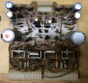
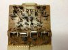
Parts came in, so I was able to rehab one driver board. Here are pics of before, cleaned, and after.
5F6CD6B1-086F-46C7-8DCF-B63B941DC989_1_201_a.jpeg 1702B405-0000-4A0C-9951-5CAE385BC7C6.jpeg 8D78FBD5-80E6-4724-9E8E-D20B3FC40EF6.jpeg

Put the board in the left (front channel) position, but still no sound. :thumbsdown: In fact, all the symptoms are the same. No movement of power meters, speaker relay clicks out if I plug in headphones.

I did test the resistors as I pulled them out. All of the 180 and 150 Ω ones were open, all of the 4.7 Ω ones were reading ok in terms of resistance. All e-caps were withing spec. So, I'm thinking the trouble is not with the driver board, but somewhere else? Going into protection with a headphone jacked int is very suspicious. What might that indicate?
 
No movement of power meters, speaker relay clicks out if I plug in headphones.
That might be entirely normal, I have seen a few amplifiers that do that.
Going into protection with a headphone jacked int is very suspicious. What might that indicate?
I don't think it is going into protection? - the action of plugging in the headphones is almost certainly 'by design'(?) opening the speaker relay. I just checked the schematic - the action of plugging in the headphones (front or rear) opens a contact that removes power from the speaker relay. ;)

There are a lot of fuses in that thing, have you checked these? have you checked all the PSU voltages are getting to the right places? If for example, you have lost the +/-46V supplies (2 fuses), or the +/-38V (6 fuses) it will be silent. ;)
 
Last edited:
Back
Top Bottom