• The move to the new server is done. There are some software and database maintenance updates in process. This has us passing the hat around to help out. We appreciate any donations. Seriously, even a dollar helps. The payment page may be found here - https://www.audiokarma.org/support.html

QRX-8001 no sound

Had time to do some tests today.

If I put the restored driver board in the Rear position with no board in the front position, the speaker relay does not click.

Looking at the schematic, I found some of the voltages to measure on the driver board. I put the restored driver board in the Front position, connected the pre-amp 4 pin connector. I left the rear board out so I could test voltages on the pins. Set selector to Front A. Here are the voltages I get in the order: pin #, Schematic voltage, measured VDC on DBT, measured VDC on full line:

18, -44, -43.2, -55
19, -38, -39, -40
29, +42, +36.7, +45.9

I checked the voltages at F06, 07, 08, 09 and all read +40VDC.

Tried setting DC offset on L and R front channels, I was getting 12 and 7 mV, respectively, but no response to VRs.

Same for setting bias. I was getting no current reading at all. An initial surge at power up of a few milliamps, then zero. No change moving VRs.

I have to confess, I'm lost.:dunno:

Can you scope the input of the driver board? Have you done that yet? Then you can follow the signal through each stage until it stops.
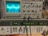
I have checked for signal input to the board, and it's there. As I look at the "big picture" right now, I've got at least two problems. 1. speaker relay clicks with just the front driver board in, but no sound. 2. Speaker relay does not click with the driver board in the rear position. So, there's at least two issues here to solve. Working on the front issue first. Yes, I could move on to tracing the signal if my voltages to the board look right.
 
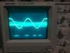
Was able to do a test today. Using the antenna input, I input a signal at a quiet spot on the dial (98 MHz), and scoped the L channel signal at the tape out and the input to the front driver board. Got a clean sine wave at the tape out, but input to the driver board is very different and noisy. Scope has both signals on screen.

48AF1996-CC11-4937-BE8D-0140108DAC9A.jpeg 25500343-E1E1-4D3D-BE70-7FB1CDC7F712.jpeg

So, looks like I have an issue in the preamp? There is signal there, but much smaller and distorted than the tape out port.
 
Try injecting audio into the 4 channel tape play jacks, and turning on 4 channel Tape monitor. If you get a good signal to the driver board at that point I bet a cup of coffee that you have bad feedthrough rivets on the F-2634 board (as I suggested in a previous post in this thread). All of the signals go through that board except the 4 channel tape monitor.
 
Try injecting audio into the 4 channel tape play jacks, and turning on 4 channel Tape monitor. If you get a good signal to the driver board at that point I bet a cup of coffee that you have bad feedthrough rivets on the F-2634 board (as I suggested in a previous post in this thread). All of the signals go through that board except the 4 channel tape monitor.
I hear what you are saying, and noticed that Tape II is after the quad processing boards while studying the schematic this morning.

However, I discovered a stupid mistake when doing the tests in my previous post: volume was all the way down :oops:, so no way to get a signal from the pre-amp in that situation! :no:

I actually tested the signal in and out of f-2636 volume & filter board, and that was good.

Then did same test as previous post with antenna signal in and monitoring Tape 2 out and signal from the pre-amp to the driver board. Got a matched signal on both front channels with volume knob at about 7. Top signal is Tape 2 out, bottom is signal from the pre-amp:
421D3E5A-731A-44B3-8464-EF97ED37300E.jpeg

Put the quad boards in and checked rear channels in synthesizer mode. All good.

Then started checking the signal path on the driver board f-2624. I had signal at the base of TR01, but no signal at the base of TR03. R13 and R15 are jumpers on my board, so checked the signal at R13, and I've got a clipped signal. It seems to change each time I measure it, sometimes it's only static, but here is the image of the clipped signal:
DC47BE67-06C5-4333-BF32-7A6F83230C2D.jpeg

I then checked the other channel at R14 (again a jumper), and I have a similar clipping here:
E37B9AD2-5E9F-49AA-AC6E-0D1516085927.jpeg

So, looks like TR01 and 02 need replacing, then see what I get. TR01-04 are 2SC1708. I see @Hipocrates has mentioned using KSC1815/1845/945C in his thread on creating replacement f-2624 boards. Can anyone recommend what should be used here? I believe I have all of those on hand.
 
Yep, KSC1845F for TR01-04. You can use KSA1220/KSC2690AYS for the four TO-126, and MJE15032/33G for the TO-220 driver transistors if need be.
 
Yep, KSC1845F for TR01-04. You can use KSA1220/KSC2690AYS for the four TO-126, and MJE15032/33G for the TO-220 driver transistors if need be.
Thanks, I was just realizing that TR01/03 and TR02/04 are the differential pair. Should all 4 be replaced and should the pairs be gain matched?
 
Thanks, I was just realizing that TR01/03 and TR02/04 are the differential pair. Should all 4 be replaced and should the pairs be gain matched?
Yes, they are the input pairs. Match them as close as you can to help keep the DC offset more stable. But on these boards the DC Offset will be bouncing all over the place anyways. But the closer the match, the less variation there will be.
 
Just as a note, I seem to vaguely remember having an issue trying to run a QRX-x001 with just one driver board installed. If I remember correctly there is a voltage fed through the driver board physically on the left to the one physically on the right. I think it was the 43 volts that goes to the 180 ohm resistors. I think it came in on pin 5 of the left driver board, and went back out on pin 28 (5 and 28 are connected together on the boards). I believe pin 28 of the left driver board was connected to 5 of the right driver board, providing 43 volts to the right driver board. This meant that trying to run the unit with no driver board in the left socket, and a good driver in the right, the unit would not function . Please bear with me if this is not correct, but I remember spending a lot of time on the issue, and I think it was on a QRX-x001, but cant be sure due to my CRS (can't remember s***)o_O.
 
Last edited:
Just as a note, I seem to vaguely remember having an issue trying to run a QRX-x001 with just one driver board installed. If I remember correctly there is a voltage fed through the driver board physically on the left to the one physically on the right. I think it was the 43 volts that goes to the 180 ohm resistors. I think it came in on pin 5 of the left driver board, and went back out on pin 28 (5 and 28 are connected together on the boards). I believe pin 28 of the left driver board was connected to 5 of the right driver board, providing 43 volts to the right driver board. This meant that trying to run the unit with no driver board in the left socket, and a good driver in the right, the unit would not function . Please bear with me if this is not correct, but I remember spending a lot of time on the issue, and I think it was on a QRX-x001, but cant be sure due to my CRS (can't remember s***)o_O.
Post #36...
put both driver boards in. Set BIAS (about half on DBT) and DC Offset on both when both are in, it's necessary, and go from there.
:rolleyes: Nobody listens....
 
Post #36...
put both driver boards in. Set BIAS (about half on DBT) and DC Offset on both when both are in, it's necessary, and go from there.
:rolleyes: Nobody listens....
I agree, see post #41.

Tried restored and unrestored driver board in rear position, but speaker relay does not click. So, there is another fault on the rear channel, presumably not related to the driver board.

Tried setting bias, but there is NO response when I move the trimmers, and current reading is zero. I don't believe I had both driver boards in when I tried to set bias, so I can give that a try this morning, but one is unrestored at this point. Speaker relay will not click, so no way to set DC offset.
 
I agree, see post #41.

Tried restored and unrestored driver board in rear position, but speaker relay does not click. So, there is another fault on the rear channel, presumably not related to the driver board.

Tried setting bias, but there is NO response when I move the trimmers, and current reading is zero. I don't believe I had both driver boards in when I tried to set bias, so I can give that a try this morning, but one is unrestored at this point. Speaker relay will not click, so no way to set DC offset.
What part of needing both boards in is it that you fail to understand? Replace at least the fusible resistors in the other board. If you don't move the trimmers, the DC Offset should be close enough to allow the relay to click in.
 
When I looked at those oscilloscope traces I thought it looked suspiciously like it was PSU related (missing rail), rather than faulty transistors. :dunno: Thus the chat about needing both driver boards inserted because of possible interlinking of PSU connections struck a chord with me.....
 
OK, was able to set the bias at about half (15 mA) on DBT with both boards in. Relay still did not click in.

Sorry, I did not understand that it was necessary to have both boards in to function in 2 channel mode. I assumed it was like a 2 channel receiver, such as the Eight, where you can focus on a fault in one channel and leave the other channel board out. Entirely my fault.
 
OK, was able to set the bias at about half (15 mA) on DBT with both boards in. Relay still did not click in.

Sorry, I did not understand that it was necessary to have both boards in to function in 2 channel mode. I assumed it was like a 2 channel receiver, such as the Eight, where you can focus on a fault in one channel and leave the other channel board out. Entirely my fault.
No problem. However did you replace the fusible resistors in the 2nd board? If not, that is a must.
 
Sound! :banana:

Replaced all fusible resistors on the rear driver board. Thought I'd give the board a try before replacing transistors. With both boards in, relay clicked! Set all DC offsets and bias on DBT (set 15 mA bias). As you stated, @Skywatcher the offset bounced around a bit, bias was very steady. Power meter movement in all 4 channels on Synthesizer Hall as volume is moved up. Then connected my test speakers, and I've got sound on all 4 channels! :jump:

Initial testing of several switches shows some must be dirty. The Synthesizer Surround switch in yields sound only on the rear channels (fronts become very weak). Moving speaker selector switch to 2 channel drops the left front channel. So some more cleaning work beyond the initial cleaning I did a few weeks ago.

Any immediate things I need to check/do? Otherwise, I will finish restoring the rear board: replace e-caps and the VD1212s. Any need to replace TR01-04 since they seem to be ok?

Thanks for keeping me on track @Skywatcher, @AE Bob, and @Hyperion ! Looking forward to continuing the restoration! :beerchug:
 
Sound! :banana:

Replaced all fusible resistors on the rear driver board. Thought I'd give the board a try before replacing transistors. With both boards in, relay clicked! Set all DC offsets and bias on DBT (set 15 mA bias). As you stated, @Skywatcher the offset bounced around a bit, bias was very steady. Power meter movement in all 4 channels on Synthesizer Hall as volume is moved up. Then connected my test speakers, and I've got sound on all 4 channels! :jump:

Initial testing of several switches shows some must be dirty. The Synthesizer Surround switch in yields sound only on the rear channels (fronts become very weak). Moving speaker selector switch to 2 channel drops the left front channel. So some more cleaning work beyond the initial cleaning I did a few weeks ago.

Any immediate things I need to check/do? Otherwise, I will finish restoring the rear board: replace e-caps and the VD1212s. Any need to replace TR01-04 since they seem to be ok?

Thanks for keeping me on track @Skywatcher, @AE Bob, and @Hyperion ! Looking forward to continuing the restoration! :beerchug:
You can always revisit the driver boards later, but I myself wouldn't hesitate to replace TR01-04 to lower the noise floor.
As far as the Synth surround, someone may have been in it before and possibly removed the blend resistors, or messed with the pots. But clean all the switches as thoroughly as you can. The quad boards can be attacked later since they are very easy to remove. But if trouble persists, the pass through joints on the board they plug into may need attention unless someone already pinned them. You can recap the quad boards without creating problems as long as your solder skills can handle it. I'm pretty sure yours can. :D Use Nichicon UKL (low leakage) for any orange caps unless they are small values where you can use film. UPW will be fine for all the grey and black caps there.
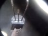
 
As I have said in earlier posts, there is almost always issues with the feedthroughs on the F-2634. I do not pin them, I just make a large solder fillet between the rivet and the foil, on both sides of the board. I have never seen where a rivet is open in the middle, so I see no reason to place a wire through the rivet. The issue (IMHO) is that the board was wave soldered when manufactured, and this provided only a very thin membrane of solder between the rivet and the foil, which has fractured with a "ring crack" after many heat cool thermal cycles.. You can physically see the "ring crack" issue on many of the rivets. Creating a thick solder bridge between the foil and rivet prevents this from reoccurring, the same way hand soldering ring cracks around stake pins connectors and component leads prevents reoccurrence of ring cracks

I also sometimes see issues with noisy / intermittent transistors on the F-2087 QS matrix PC board. They are the ones where the leads turn black, and IMHO develop a noisy leakage path between leads across the transistor body due to the plating migrating onto the body as it tarnishes (see photos). Many times the leakage path is not visible though.
0126171019a.jpg 0804170810b.jpg
 
Yes I too have seen that "oil slick" look on noisy transistors. It is conductive causing pops, crackles, rattles, and other unwanted toe curling sounds. And will eventually go "poof! if not replaced. Usually the tell-tale signs are tarnished to black leads pointing to you calling out for "replace me"... :D And before anyone asks, NO, cleaning does no good whatsoever except to "please" the eyes. :beatnik: And Yes, replacing them doesn't ire the :bowdown: "Quad Genie" at all as long as the replacements are compatible. :thumbsup:
 
Back
Top Bottom