• The move to the new server is done. There are some software and database maintenance updates in process. This has us passing the hat around to help out. We appreciate any donations. Seriously, even a dollar helps. The payment page may be found here - https://www.audiokarma.org/support.html

QRX-8001 no sound

As I have said in earlier posts, there is almost always issues with the feedthroughs on the F-2634. I do not pin them, I just make a large solder fillet between the rivet and the foil, on both sides of the board. I have never seen where a rivet is open in the middle, so I see no reason to place a wire through the rivet. The issue (IMHO) is that the board was wave soldered when manufactured, and this provided only a very thin membrane of solder between the rivet and the foil, which has fractured with a "ring crack" after many heat cool thermal cycles.. You can physically see the "ring crack" issue on many of the rivets. Creating a thick solder bridge between the foil and rivet prevents this from reoccurring, the same way hand soldering ring cracks around stake pins connectors and component leads prevents reoccurrence of ring cracks

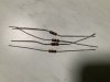
I also sometimes see issues with noisy / intermittent transistors on the F-2087 QS matrix PC board. They are the ones where the leads turn black, and IMHO develop a noisy leakage path between leads across the transistor body due to the plating migrating onto the body as it tarnishes (see photos). Many times the leakage path is not visible though.
View attachment 2247982 View attachment 2247983
I do pin them to reduce the chances of solder shrinkage over time. (I want NO comebacks biting me down the road) But simply sucking off the old solder and fresh resoldering works fine as long as you're sure both sides are good. :thumbsup: In fact that's what I did to one of my 9090DB Dolby boards and it is 10 years since still working 100% fine.
 
When I run into noisy 4 channel modes, I replace all the transistors on that board with 2SC1815 and 2SA1015 transistors. The quad decoding always seems to be better after replacement (rear channels amplitude more compatible with the front channels), and no more noises.
 
Lots of great advice here @Skywatcher and @AE Bob ! I will replace TR01-04 on the drivers as all of them have black oxidized legs. Great info on how those transistors can short out, Bob. Those pictures really tell the story. I've got about 80 KSC1845F on hand, so will be able to find some matched pairs.

I believe at least part of the issue with dropped sound for some setting is cracked solder on the pass throughs of f-2634. In one of the modes when I press on the board a bit a channel came in, so those pass throughs will need attention. Is there a thread documenting the process? Would just like to see how to get at all parts of the board. I believe there are 50-some pass throughs to do.
It's a real PITA to get access to that board being sandwiched between 2 others and under a lip of the chassis... I loosened the front panel enough to "stretch" the tuner string to it's limit and there was just enough space to get that board out to work on. But some of the joints can be done without removing it. Of course they all will need done anyways.. It is much easier to destring the tuner to get it out of the way to get the board out. But can be done either way. I chose to destring my 9001 making life a lot easier. And restringing really is pretty easy on these.. But not if you've never done it before, it's very intimidating :eek: the first time.
 
Last edited:
You really need to remove the push button switch assembly from the PC board (30 or so solder connections), to access some of the rivets on the top side. I don't completely disconnect the board, but I remove all of the plugged in wires on the front right, and de-solder one at the left back (I think that is all), then get the board out by moving the front panel forward on the right after removing control nuts and screws (I leave some screws in the far left). I slip the dial cord off one of the idler pullies to give enough slack to move the panel forward enough to get the board out. I then suck the solder from all of the terminals of the push button switch and remove it. I solder both sides of all of the rivets (frequently going from top to bottom more than once). Sometimes I will suck all the solder from the rivet core, if I am having issues with the solder bubbling. After re doing all of the rivets I clean the push button switch assembly, reinstall it, and put it all back together. It is a BIG JOB, at least as difficult as the x0x0DB Dolby board repair, maybe worse.
 
Yes, things are moving forward. Just by pressing on some of the feed throughs on the quad plugin board I located the one that was causing the dropped channel in two channel mode. Just out of curiosity I put some solder on that rivet and the channel came back in. Found a good video that walks through the disassembly process to get the f-2634 board out here. So at this point I'll need to order a set of lights (3 of the power meter lights are out or weak, dial pointer burned out). I can then work through the disassembly and pin/re-solder f-2634 and replace the lights.

In the mean time I can replace TR01-4 and the VRs on the driver boards. I've also got the parts to re-cap the PS. Some time in there I'll need to refinish the case. One side has veneer missing around the bottom. Not sure if I should re-veneer the whole side, or if a repair can be done.

Thanks again for all the help from everyone, will update as progress is made!
 
After listening through my test speakers for a few days, I just had to connect it up to som real speakers. Really impressed with the great sound! Next up will be re-soldering all of the pass through and replacing lights.

B6823444-DF1F-4BFA-A716-8B0F999EE824.jpeg
 
Replaced the power meter light bulbs, but no difference in the lights that are on. Right rear meter light is fully on, Right front meter light is about half brightness, and the other two meters don't light. This can be seen in the photo in the previous post. So, seems the bulbs may not have been burned out after all. Any idea where the issue may be?
 
There is a small resistor (10 ohms I believe) on the PC board on the back of the meter, that is in series with the lamps. I have seen that resistor open up several times.
 
There is a small resistor (10 ohms I believe) on the PC board on the back of the meter, that is in series with the lamps. I have seen that resistor open up several times.
Thanks Bob, I saw those last night when I was looking at the schematic. Then I looked at the SM and saw that they were fusible resistors! :mad: They are all 22 Ω. I have a couple of those on hand, and so replaced the one for the dial pointer, and viola, the light came on. The original measured 500 kΩ! I'll need 4 more for the meters, but I've only got one on hand. May need to scrounge around to see if I can find some. Otherwise, what range might work? I've got a bunch of 10 and 150 Ω resistors from replacing those on the driver boards.
 
You could put a couple of 10 ohm in series (making 20 ohms). That would only be 2 ohms off, and likely not noticeable in the lamp brightness.
 
Thanks Bob, I saw those last night when I was looking at the schematic. Then I looked at the SM and saw that they were fusible resistors! :mad: They are all 22 Ω. I have a couple of those on hand, and so replaced the one for the dial pointer, and viola, the light came on. The original measured 500 kΩ! I'll need 4 more for the meters, but I've only got one on hand. May need to scrounge around to see if I can find some. Otherwise, what range might work? I've got a bunch of 10 and 150 Ω resistors from replacing those on the driver boards.
Like Bob says, you can use two 10 Ohm in series and be close enough, but there is limited space at the meters. You can check on that and if there is room, use 'em. Alternatively I can mail you four 22 Ohm metal film (or oxide if I have them) resistors if you need them. No sense in spending 8 bucks in shipping for a couple of seldom used resistors, unless you're adding them to another needed order. You replacing the bulbs is good anyways since you don't really know how many hours are on them. Now you know they are "zero" hours. :D
 
Like Bob says, you can use two 10 Ohm in series and be close enough, but there is limited space at the meters. You can check on that and if there is room, use 'em. Alternatively I can mail you four 22 Ohm metal film (or oxide if I have them) resistors if you need them. No sense in spending 8 bucks in shipping for a couple of seldom used resistors, unless you're adding them to another needed order. You replacing the bulbs is good anyways since you don't really know how many hours are on them. Now you know they are "zero" hours. :D
Thanks guys. I was able to locate some 26 Ω resistors, so that will be close enough, I think. They are carbon film, which shouldn't be a problem in this application, right?

Yes, the way they are mounted on the meters there is not much room in there, so I could put two 10 Ω in series, but I think I'd have to get creative about the mounting. I had just two 22 Ω resistors left over from when I restored the driver board on my 9090, otherwise, I've had no call for them. As you say, they are seldom used. It's such a massive undertaking to open the 8001 up to get at these components, that I don't wan to do it again! :no:

IMG_1030.jpg
 
Thanks guys. I was able to locate some 26 Ω resistors, so that will be close enough, I think. They are carbon film, which shouldn't be a problem in this application, right?

Yes, the way they are mounted on the meters there is not much room in there, so I could put two 10 Ω in series, but I think I'd have to get creative about the mounting. I had just two 22 Ω resistors left over from when I restored the driver board on my 9090, otherwise, I've had no call for them. As you say, they are seldom used. It's such a massive undertaking to open the 8001 up to get at these components, that I don't wan to do it again! :no:

View attachment 2264471
I'm not so sure I would want to use carbon film since they generate heat for voltage drop, unless they are at least 1/2 watt. PM me your mailing address and I'll toss a few in an envelope, paste a stamp on it, and send them on their way. Might as well do 'er right so it lasts many decades, and all the lamps the same brightness.
 
As I looked at how the resistors were mounted on the meter PCB, it seemed a bit odd. I decided it made sense to mount the new resistors on the opposite side of the board, and perpendicular to the originals, such that any heat that might be generated would not affect anything around it. I think this works well:

977EC158-8521-4AFC-8C80-BCCCA8BC23B9.jpeg

After doing tests on DBT that the lights all worked and my work pinning the 4 channel board was all ok, I reassembled the unit. All functions are now workin on all channels! I also refinished the case, which turned out well. It’s playing beautifully now. Great clarity, detail, low distortion compared to my QR receivers. All that’s left is replacing the VRs on the driver boards and re-capping the PS.

B81A13A3-D215-433B-B9C3-DE0EF4B71B02.jpeg
 
Nice one, good to see you got her up and running, they are a pretty nice sounding unit, I have had a few 8001's and 9001's across my bench and I have always been impressed.
They are a lot of work though!! Especially the 9001, but once you've done one, they don't seem so bad.....

Enjoy, crank it up!!
Thanks Kev, this is going to replace the QR-6500/QSD-2 in my main quad system. I went after the 8001 because they are much less expensive than a 9001 and I did not need to deal with the dolby board. You get an extra input/output with the "Adapter" switch, though it is only 2 channel. I agree it was intimidating at first, but going slow and having patience pays off. Looking back I'm kind of surprised it was not more difficult for me, but I am much better at repairs now than I was a couple of years ago. That YouTube video of taking apart the unit and pining the pass throughs was also a ton of help and gave me confidence to proceed.

Thanks for the great help from @Skywatcher and @AE Bob and their patience with me!

I'll put some 22Ω metal oxide/film resistors on my next Mouser order. I've mounted those carbon film resistors on the meter PCBs such that it will be easy to replace them later without having to take everything apart.
 
Back
Top Bottom