

You are using an out of date browser. It may not display this or other websites correctly.
You should upgrade or use an alternative browser.
You should upgrade or use an alternative browser.
Register to hide this ad

Should be easy enough to see with just the wood case removed. Looking top down into the unit, there is a circuit board (F-2436) mounted horizontally that sits beneath two plug-in circuit boards (F-2087 and F-2088) that are oriented vertically and behind the dial scale (front right portion of the chassis). These are clamped in place with a black painted steel bracket.
The horizontal circuit board is the one that requires re-pinning as it has a multitude of vias (solder joints that connect printed circuit traces on both sides of the board) some of which are visible without any major disassembly. If you can see these solder joints (all are round points, slightly larger than 1/8" diameter) and they have a small piece of wire passing through the center of the via then folded over on the board and soldered to the adjoining circuit trace, then it's been re-pinned.
Further, if your 9001 is not having any problems with dropped or intermittent loss of sound in one or more channels, it has probably been done, since it would almost certainly not be working right without having been re-pinned.
Should be easy enough to see with just the wood case removed. Looking top down into the unit, there is a circuit board (F-2436) mounted horizontally that sits beneath two plug-in circuit boards (F-2087 and F-2088) that are oriented vertically and behind the dial scale (front right portion of the chassis). These are clamped in place with a black painted steel bracket.
The horizontal circuit board is the one that requires re-pinning as it has a multitude of vias (solder joints that connect printed circuit traces on both sides of the board) some of which are visible without any major disassembly. If you can see these solder joints (all are round points, slightly larger than 1/8" diameter) and they have a small piece of wire passing through the center of the via then folded over on the board and soldered to the adjoining circuit trace, then it's been re-pinned.
Further, if your 9001 is not having any problems with dropped or intermittent loss of sound in one or more channels, it has probably been done, since it would almost certainly not be working right without having been re-pinned.
Thank you for your reply. In looking at the board I cant say that I see any pins sticking out but all of the points I have seen in another photo are shiny solder not dull solder if you know what I mean. I am attaching a photo if that helps.
Another thing is that the 2X switch has been physically locked out, the 25V Transistor has been re-pasted and there is a split panel for pre and main amp on the back making me think it has been updated.
Attachments

Ok. It looks like the vias may have been resoldered, but not pinned, from that photo. That will be good enough to work for a while, but will probably experience problems with channel drop out again at some point. The problem is that the vias are too large, they do not have copper plating through to the opposite side of the board (as is done in modern PCB manufacture) and the solder used ag the factory was too porous and had a tendency to crack easily under heat and mechanical stress.
Newer lead bearing solder (not the lead free ROHS garbage) holds up better than the stuff Sansui used at the factory but will still end up with hairline cracking, causing intermittent problems in the signal path.
Pinning overcomes this by effectively extending the solder joint beyond the via onto the foil on the surface of the board. This eliminates failure from expansion and contraction that leads the solder within the vias to crack over time, so continuity is maintained.
In any case it sounds like whoever worked on yours did a fairly nice job, even if they didn't pin it. May have been an older resto done before the need for pinning was widely recognized.
Ok. It looks like the vias may have been resoldered, but not pinned, from that photo. That will be good enough to work for a while, but will probably experience problems with channel drop out again at some point. The problem is that the vias are too large, they do not have copper plating through to the opposite side of the board (as is done in modern PCB manufacture) and the solder used ag the factory was too porous and had a tendency to crack easily under heat and mechanical stress.
Newer lead bearing solder (not the lead free ROHS garbage) holds up better than the stuff Sansui used at the factory but will still end up with hairline cracking, causing intermittent problems in the signal path.
Pinning overcomes this by effectively extending the solder joint beyond the via onto the foil on the surface of the board. This eliminates failure from expansion and contraction that leads the solder within the vias to crack over time, so continuity is maintained.
In any case it sounds like whoever worked on yours did a fairly nice job, even if they didn't pin it. May have been an older resto done before the need for pinning was widely recognized.
Thank you for your time and attention. I am learning allot.
Tom

kevzep
Its all about the Music
I've done 3 in the last 6 months, and a QRX8001 yesterday. Take a picture from the top on the right hand side behind the tuner dial face, you'll see a relay down there, this is the area you need to photograph.
Nice clear in focus picture is the easiest way to be able to tell you for sure...
Nice clear in focus picture is the easiest way to be able to tell you for sure...

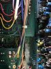

The 4 pole relay has been removed (white rectangle in second photo marked RL02 on board), and jumpers installed, as part of the modification eliminating the stereo power X 2 mode. From what I can see in these new pictures, it doesn't look as though any pinning was done. Looks like RL01 - which is a small Hitachi reed relay - (also part of the power strapping mode circuit) has also been removed.
Back in the day, QuadBob (do some searching on here if you want the backstory on that) was big on eliminating the power X 2 mode, on the basis that it was unstable and unneeded. I'm not much convinced of his claims or of the need for disabling it - all of mine still have it and it works fine though seldom used - but it appears whoever did work on this unit followed that line of thinking. I don't see anything in the provided photos that would cause me to be critical of the work done, but to this point have seen only a few pictures of a small portion of the unit so can't really say much on that good or bad.
I believe QRXRestore (and they largely wrote the book on proper restorations of the QRX-8001/9001 after the QuadBob saga died down) leaves the power X 2 mode intact, but perhaps they made some tweaks that corrected the instability QuadBob liked to cite. I know they do some upgrades to the driver board, which is the source of most power amp instability in this series of models (including 8080DB and 9090DB which used the same basic driver board).
Last edited:
Ok, the fact that the 25 Volt PS Transistor looks re-pasted and the added RCA preamp/ amp connections made be think that may be the case. I have read some of the Quad Bob stuff but looks like it somehow ended on a sour note. The X2 switch is physically locked out. You cannot move the switch into that mode. Another person commented that the board may not have been pinned but re-soldered.
Thank you for your time
Tom
Thank you for your time
Tom
Sounds like a stop was installed on the rotary switch for the speaker mode, in addition to portions if the circuitry being removed. Not a big deal if done right, but was probably unnecessary. No matter, what's done is done, I think your potential concern going forward is the possibility of a failure of the vias again. Hopefully that doesn't happen, but without pinning having been done, it is a possibility.
I'd point out that the first 9001 I repaired almost 20 years ago (when knowledge on the subject was far more limited than now) was not pinned, just new solder flowed in the vias, and it still works today without a recurrence of the failure. I did remove all existinig solder from the vias with a vacuum desoldering rig and used new high quality lead solder to redo them. Depsite that track record, if I were doing another one now (or redoing the one I just spoke of) I'd pin all the vias just for extra peace of mind.
I'd point out that the first 9001 I repaired almost 20 years ago (when knowledge on the subject was far more limited than now) was not pinned, just new solder flowed in the vias, and it still works today without a recurrence of the failure. I did remove all existinig solder from the vias with a vacuum desoldering rig and used new high quality lead solder to redo them. Depsite that track record, if I were doing another one now (or redoing the one I just spoke of) I'd pin all the vias just for extra peace of mind.

Despite that track record

kevzep
Its all about the Music
Here you go, this is what it looks like when the pass-throughs have been pinned. This is a QRX8001 I happen to have on the bench at the moment. Its the same board in the 9001.
Its quite time consuming, and there is quite a bit of disassembly required, you have to remove the front of the chassis. The Bottom picture shows how far you have to pull the front panel of the chassis to get the boards out.
I would remove that stop on the selector, and I would remove that hack where the relay goes and return it back to factory.
I work on a lot of these QRX's, and I have never seen one go unstable under any condition, so I am not sure what thats all about.
Ok very clear now. The pins are folded over the traces and soldered.Here you go, this is what it looks like when the pass-throughs have been pinned. This is a QRX8001 I happen to have on the bench at the moment. Its the same board in the 9001.
Its quite time consuming, and there is quite a bit of disassembly required, you have to remove the front of the chassis. The Bottom picture shows how far you have to pull the front panel of the chassis to get the boards out.
I would remove that stop on the selector, and I would remove that hack where the relay goes and return it back to factory.
I work on a lot of these QRX's, and I have never seen one go unstable under any condition, so I am not sure what thats all about.
View attachment 1499695 View attachment 1499696 View attachment 1499697
Thanks again.
Tom
kevzep
Its all about the Music
Yes thats correct, you just have to scrape a bit of the green coating off the track for the solder to flow.Ok very clear now. The pins are folded over the traces and soldered.
Thanks again.
Tom
I use flux when I am doing this because even though the solder has flux in it, adding some to the work area as well makes a much nicer job of it, the solder flows much better.
Lucky I just happened to be doing one!!
Hello,
I purchased another QRX-9001 because I thought it was a steal. I blew out all of the insects and Deoxed the switches I could reach. Upon power up it has a hum (only) in the left rear channel and what appears to be a large white resistor on the Speaker switch is getting hot and burning the clear plastic cover over it after about 5 to 10 minutes of use. That meter does not function. All the others do. All other channels appear to work OK. The speaker switch is in the 4 channel A position. The speaker outputs don't appear to function but the quad headphones I have do. I have a copy of the service manual but don't have enough experience to read it. I think I am going to have to send it off to be repaired but wanted to know if you had any hints first.
Thanks
kevzep
Its all about the Music
Send it off to get repaired, these units are very complex and not great for people who have little experience.Hello,
I purchased another QRX-9001 because I thought it was a steal. I blew out all of the insects and Deoxed the switches I could reach. Upon power up it has a hum (only) in the left rear channel and what appears to be a large white resistor on the Speaker switch is getting hot and burning the clear plastic cover over it after about 5 to 10 minutes of use. That meter does not function. All the others do. All other channels appear to work OK. The speaker switch is in the 4 channel A position. The speaker outputs don't appear to function but the quad headphones I have do. I have a copy of the service manual but don't have enough experience to read it. I think I am going to have to send it off to be repaired but wanted to know if you had any hints first.
Thanks
Make sure you send it somewhere that knows about Sansui QRX's.
Not sure where you are as you haven't filled out the information in your Avatar, if we know where you are we might be able to offer some guidance.


