

You are using an out of date browser. It may not display this or other websites correctly.
You should upgrade or use an alternative browser.
You should upgrade or use an alternative browser.
Quad ESL-63 rehab
- Thread starter mrehorst
- Start date


mrehorst
Super Member
I marked one of the original diaphragms (that will be replaced) with a permanent marker today. I put two marks, 500 mm apart on the film. Then I cut the film free of the grid it was glued to, laid it flat, and measured the distance between the two marks- 496.5 mm. 3.5/500= 0.007 - i.e 0.7% stretch. I'll check the other 3 diaphragms as I remove them to reglue the stators.
When I put new film on the stretcher table, I'll inflate the tube just enough to take out the wrinkles, then put two marks on the film 496.5 mm apart, then stretch the film by putting more air in the tube until the marks are 500 mm apart, then glue the grid to the stretched film.
When I put new film on the stretcher table, I'll inflate the tube just enough to take out the wrinkles, then put two marks on the film 496.5 mm apart, then stretch the film by putting more air in the tube until the marks are 500 mm apart, then glue the grid to the stretched film.
mrehorst
Super Member
I checked the other 3 diaphragms before removing them and found about 2.5mm of stretch on the film. The measurement is pretty "iffy". The film doesn't like to lay flat so I tape it down and pull out the wrinkles. It would be easy to make a 1 mm error.
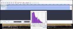
I also checked resonance of the last diaphragm before I removed it. I thumped it with my finger and recorded the drum-like sound. Then I opened the recording in Audacity and zoomed in on one of the thumps, counted out several cycles, and measured the time those cycles took. I got 98 Hz resonance. I checked several of the other thumps and got the same number. When I take the other speaker apart, I will check each diaphragm the same way before I remove it. When I put in new diaphragms, I'll figure out the amount of stretch to use to give the same resonance.
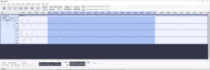
I finished cleaning up the grids and stators and started gluing them. It will take a couple days for all four to be reglued. While that is going on I will start taking the other speaker apart and cleaning off all the old tape residue.
I also checked resonance of the last diaphragm before I removed it. I thumped it with my finger and recorded the drum-like sound. Then I opened the recording in Audacity and zoomed in on one of the thumps, counted out several cycles, and measured the time those cycles took. I got 98 Hz resonance. I checked several of the other thumps and got the same number. When I take the other speaker apart, I will check each diaphragm the same way before I remove it. When I put in new diaphragms, I'll figure out the amount of stretch to use to give the same resonance.
I finished cleaning up the grids and stators and started gluing them. It will take a couple days for all four to be reglued. While that is going on I will start taking the other speaker apart and cleaning off all the old tape residue.
Last edited:
mrehorst
Super Member
I tore into the second speaker yesterday. The foam tape is a different color and density from the other one, so I think someone has been working on these before. The stators all seem solidly glued, but I'm going to pull the drivers and probably bust the stators loose and reglue them anyway. I don't want to have to go through this process again in my lifetime.
mrehorst
Super Member
It looks like the stators are glued so solidly that I'll break them if I try to break them loose, so I'm going to leave them alone. One driver's diaphragm has come loose in one corner, so I'll replace that diaphragm. The more I work on these, the more I wonder how they ever managed to ship these things around the world and have them arrive in working order. The driver enclosure frame consists of two main vertical aluminum pieces with an additional four, skinny sticks, all screwed to plastic top and bottom plates, and that whole thing is ultimately screwed to the plastic box that holds the electronics. There's no cross bracing. I think they were relying on the tape holding the metal grids to give them some additional rigidity. I can see doing that, except for the tape nonsense. The grids should have been screwed to the top and bottom plates, not taped. And a thin walled plastic box for the electronics? How did this cheesy, yet overly-complex design ever get to manufacturing?
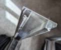
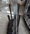
The more I look at it, and the more tape residue I struggle to clean off these things, the more I am tempted to just rebuild them into a solid structure, either welded steel or t-slot aluminum, with the extra bass panels at top and bottom, effectively making them into ESL-969s. I have ready access to welders and materials at the makerspace. There are 17 wires that connect between the electronics and the drivers. It would be nice if the electronics box and the driver enclosure could just plug into each other.
I did some study on FFT and decided to use the spectrum plot with a Hann window to read the resonance of the drivers. After testing the three good drivers in the second speaker, I came up with 92 Hz as the target resonance for new diaphragms, though I'm inclined to go a little higher to ensure adequate tension to prevent the diaphragms from sticking to the stators. The diaphragm from the first speaker that I used to calculate resonance from the waveform gave me 98 Hz just dividing the number of cycles of the waveform by the time they took. Using FFT with a Hann window gave me a 99 Hz resonance. I'd call that pretty good agreement.
The more I look at it, and the more tape residue I struggle to clean off these things, the more I am tempted to just rebuild them into a solid structure, either welded steel or t-slot aluminum, with the extra bass panels at top and bottom, effectively making them into ESL-969s. I have ready access to welders and materials at the makerspace. There are 17 wires that connect between the electronics and the drivers. It would be nice if the electronics box and the driver enclosure could just plug into each other.
I did some study on FFT and decided to use the spectrum plot with a Hann window to read the resonance of the drivers. After testing the three good drivers in the second speaker, I came up with 92 Hz as the target resonance for new diaphragms, though I'm inclined to go a little higher to ensure adequate tension to prevent the diaphragms from sticking to the stators. The diaphragm from the first speaker that I used to calculate resonance from the waveform gave me 98 Hz just dividing the number of cycles of the waveform by the time they took. Using FFT with a Hann window gave me a 99 Hz resonance. I'd call that pretty good agreement.
mrehorst
Super Member
I did a test 6 um (I have a near infinite supply of it, and a limited supply of the 3 um film that will be used for the final install) diaphragm glue-up yesterday that reminded me of a few things from when I did this about 30 years ago, and showed me a few new things that will save me some trouble down the road. One of them was to disconnect the air pump from the tube immediately after stretching the film. The air pump connection lets air leak slowly and that can cause problems (as it did yesterday).
When I made the holes for the three center screws in the diaphragm, I used a soldering iron set to the minimum temperature that would do the job. That creates some very fine hairs that need to be removed. I don't recall how I did it back in the day (I think at the time I didn't have a temperature controlled iron, so it was HOT), so I'll have to think about that. When I am 3D printing I get rid of fine hairs on prints by hitting them with a heat gun. I'm not sure that will work for this without destroying the diaphragm. Maybe I can use the soldering iron to take off the hairs it created.
I had some difficulty getting all the wrinkles out of the film when I stretched it. The stretcher table I used 30 years ago was larger than this one, so any wrinkles ended up at the periphery of the table, well away from the driver. There isn't so much extra table with this one, so I have to modify my procedure for putting the film on the table. Yesterday I attached the film on the long sides first- it will be better to attach it on the short sides first. Fortunately, it's possible to peel the film off the tape without tearing it to reposition it.
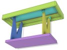
I also played with some designs for welded steel frames for ESL-989 configuration. Still thinking about it...
When I made the holes for the three center screws in the diaphragm, I used a soldering iron set to the minimum temperature that would do the job. That creates some very fine hairs that need to be removed. I don't recall how I did it back in the day (I think at the time I didn't have a temperature controlled iron, so it was HOT), so I'll have to think about that. When I am 3D printing I get rid of fine hairs on prints by hitting them with a heat gun. I'm not sure that will work for this without destroying the diaphragm. Maybe I can use the soldering iron to take off the hairs it created.
I had some difficulty getting all the wrinkles out of the film when I stretched it. The stretcher table I used 30 years ago was larger than this one, so any wrinkles ended up at the periphery of the table, well away from the driver. There isn't so much extra table with this one, so I have to modify my procedure for putting the film on the table. Yesterday I attached the film on the long sides first- it will be better to attach it on the short sides first. Fortunately, it's possible to peel the film off the tape without tearing it to reposition it.
I also played with some designs for welded steel frames for ESL-989 configuration. Still thinking about it...
Last edited:
mrehorst
Super Member
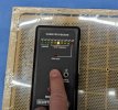
I went ahead and put masking tape on the long sides of the grid, placed the masks, and sprayed with Licron Crystal today. There were no surprises. I checked the resistivity and got 10^8 Ohms/square. Looks like it's all going to work. I'll be trying another test using the 3 um film in the next day or two.


Last edited:

mrehorst
Super Member
Much more progress today...
After I did the test described above I had to clean the diaphragm and glue off the grid. It was awful- the glue sticks so well I had to use a combo of scraping and solvents, over and over again, for about an hour to get it clean. Today I used some VHB foam tape instead of the glue and I think I will be able to peel the film off it when I'm finished testing, and maybe even be able to peel the tape off the grid.
Anyway, testing...
I have marks spaced 500 mm apart on the stretcher. I put a 6um film on it, made marks on the film directly over the marks on the table, then stretched the film until the marks were 503 mm apart, then attached the grid with the VHB tape and tested the resonance.
I also came up with a reliably consistent way to thump the diaphragm to test resonance- I glued a thread to a steel ball bearing. I just swing it until it hits the diaphragm and record the sound, then run FFT on it in Audacity. The waveform is much cleaner this way than with my previous "drumstick" tool and the result is much more consistent.
I'm going to test the remaining good, original factory diaphragm resonances, then run at least one more test with 3 um film to determine the amount of stretch to apply, and if that goes well, I'll start the actual diaphragm installs.
After I did the test described above I had to clean the diaphragm and glue off the grid. It was awful- the glue sticks so well I had to use a combo of scraping and solvents, over and over again, for about an hour to get it clean. Today I used some VHB foam tape instead of the glue and I think I will be able to peel the film off it when I'm finished testing, and maybe even be able to peel the tape off the grid.
Anyway, testing...
I have marks spaced 500 mm apart on the stretcher. I put a 6um film on it, made marks on the film directly over the marks on the table, then stretched the film until the marks were 503 mm apart, then attached the grid with the VHB tape and tested the resonance.
I also came up with a reliably consistent way to thump the diaphragm to test resonance- I glued a thread to a steel ball bearing. I just swing it until it hits the diaphragm and record the sound, then run FFT on it in Audacity. The waveform is much cleaner this way than with my previous "drumstick" tool and the result is much more consistent.
I'm going to test the remaining good, original factory diaphragm resonances, then run at least one more test with 3 um film to determine the amount of stretch to apply, and if that goes well, I'll start the actual diaphragm installs.
mrehorst
Super Member
Now that I have a very reliable way to test resonance, I'm thinking I need an equally reliable way to set the resonance before I glue the diaphragm down. The diaphragm stretcher I have works well, but I can't test or adjust the diaphragm resonance before I glue the grid to it. If the resonance isn't right after I glue it, I have to pull the diaphragm off, clean the grid, and try again- without knowing what the resonance is until after I've glued it again. Ugh.
I am going to modify the stretcher so that I can test the diaphragm resonance before I glue the grid to it. That will involve removing the floor tiles from the surface of the stretcher and cutting out the center of the stretcher so the diaphragm is free to vibrate, before I glue the grid to it. I'll have to remove the existing legs and work out some other means of support that will allow full access to the inside surface of the rim of the table for placing tape and for attaching the diaphragm to it. Maybe a two piece design with no legs on the stretcher, and legs that stand up on a base plate.
The new method of using it will be to put the film on the stretcher, inflate the tube, test the resonance by thumping the diaphragm, adjust air pressure as necessary to tune the resonance to 86 Hz, then glue the grid down on the diaphragm. That should take all the guess work out of setting the resonance.
I'll take the stretcher to the makerspace later today and make the mods. It shouldn't take long.
I am going to modify the stretcher so that I can test the diaphragm resonance before I glue the grid to it. That will involve removing the floor tiles from the surface of the stretcher and cutting out the center of the stretcher so the diaphragm is free to vibrate, before I glue the grid to it. I'll have to remove the existing legs and work out some other means of support that will allow full access to the inside surface of the rim of the table for placing tape and for attaching the diaphragm to it. Maybe a two piece design with no legs on the stretcher, and legs that stand up on a base plate.
The new method of using it will be to put the film on the stretcher, inflate the tube, test the resonance by thumping the diaphragm, adjust air pressure as necessary to tune the resonance to 86 Hz, then glue the grid down on the diaphragm. That should take all the guess work out of setting the resonance.
I'll take the stretcher to the makerspace later today and make the mods. It shouldn't take long.
mrehorst
Super Member
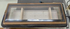
I modified the stretcher today and I think it's a winner. I cut the center out of the stretcher table and used the piece from the center as a base. I added neoprene foam around the opening in the stretcher so that when I glue the unflat driver grid to the film it will stick everywhere. The stretcher and base are two separate pieces so I can lift the stretcher off the base as needed and tilt it up for testing resonance.
This is the base- crude by effective.

And here's the stretcher with a piece of 6 um film stretched tight- no wrinkles and tight as a drum. The opening in the center is the size of the free diaphragm area on a driver, so in theory, the resonance of the diaphragm should not change much when transferring the film from the stretcher to the grid. I expect resonance may drop slightly as the film tension will probably bend the grid a little.
This is the base- crude by effective.
And here's the stretcher with a piece of 6 um film stretched tight- no wrinkles and tight as a drum. The opening in the center is the size of the free diaphragm area on a driver, so in theory, the resonance of the diaphragm should not change much when transferring the film from the stretcher to the grid. I expect resonance may drop slightly as the film tension will probably bend the grid a little.
mrehorst
Super Member
I put a 6 um diaphragm on the stretcher and tuned it to 93 Hz, then stuck it to a grid with VHB tape and checked its resonance- 92 Hz. So it looks like I can transfer the diaphragm from the stretcher to the grid without any major change in resonance. Now I have to work out an easier way to set the resonance on the stretcher so I don't have to keep recording and plotting the spectrum over and over.
I set up my AWG with an 86 Hz sine wave modulated by a 1 Hz exponential decay and it sounds a LOT like thumping the diaphragm. I think I can use that to tune the diaphragm resonance. More experiments...
I set up my AWG with an 86 Hz sine wave modulated by a 1 Hz exponential decay and it sounds a LOT like thumping the diaphragm. I think I can use that to tune the diaphragm resonance. More experiments...
Last edited:
mrehorst
Super Member
The thumping thing isn't going to work for tuning the diaphragm resonance before I glue it to the grid. I'm working on a better way to read the resonance in real-time so I can read it as I am inflating the tube. That way I can stop inflating at the target resonance and glue the grid without all the back and forth. I have some ideas to try for that, primarily, placing a speaker under the stretcher, sweeping a tone on it, and monitoring the diaphragm for maximum deflection, which should indicate resonance. I think that if I point a laser at the diaphragm and look at its reflected beam on the wall I will be able to detect maximum deflection of the diaphragm. More experiments to follow.
In case that fails, I have a microphone on order and may be able to read diaphragm resonance that way, but not sure if I can do that while the speaker is sweeping a tone.
My AWG is easily set up to do sweeps, but it doesn't display the changing frequency as it is sweeping, so I will have to manually adjust frequency. No big deal there.
In case that fails, I have a microphone on order and may be able to read diaphragm resonance that way, but not sure if I can do that while the speaker is sweeping a tone.
My AWG is easily set up to do sweeps, but it doesn't display the changing frequency as it is sweeping, so I will have to manually adjust frequency. No big deal there.
Last edited:
mrehorst
Super Member
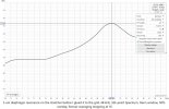
Major progress again! Trying to use a speaker is not good, thumping is great! I set up REW on my laptop and plugged in a UMIK-1 mic and switched to the RTA to plot spectrum of the diaphragm thumps in almost real time. The results indicate that this will be a good method to use to tune the diaphragm resonance while it's on the stretcher. I need to modify the stretcher to allow easy tilt-up so I can thump it, and then I will start installing new diaphragms.

It took just a few seconds to generate this plot by thumping one of the factory diaphragms. The 88 Hz resonance is very close to the 86 Hz I had obtained using my recorder and Audacity's FFT.
It took just a few seconds to generate this plot by thumping one of the factory diaphragms. The 88 Hz resonance is very close to the 86 Hz I had obtained using my recorder and Audacity's FFT.
mrehorst
Super Member
I put a 3 um diaphragm on one driver grid today. I'm letting the glue cure overnight.
It took just 4 tests to get the film up to 90 Hz resonance on the stretcher. I went a little above the 88 Hz target because I expect resonance to drop slightly when I cut the grid free of the film on the table, and to drop a little more when I spray on the Licron conductive coating (added mass -> lower resonance).
It took about 20 minutes to prep and put the film on the stretcher, stretch it to 90 Hz resonance, and apply glue to both the film and the grid. Then I waited another 20 minutes for the glue to set up and put the grid down on the film. I think I'll be able to do one or two driver grids per day, so I think I'll have the speakers back up and running like new in about a week, assuming I don't run into any more problems. I'll glue the diaphragms on all the grids first, then spray all of them with Licron.
It took just 4 tests to get the film up to 90 Hz resonance on the stretcher. I went a little above the 88 Hz target because I expect resonance to drop slightly when I cut the grid free of the film on the table, and to drop a little more when I spray on the Licron conductive coating (added mass -> lower resonance).
It took about 20 minutes to prep and put the film on the stretcher, stretch it to 90 Hz resonance, and apply glue to both the film and the grid. Then I waited another 20 minutes for the glue to set up and put the grid down on the film. I think I'll be able to do one or two driver grids per day, so I think I'll have the speakers back up and running like new in about a week, assuming I don't run into any more problems. I'll glue the diaphragms on all the grids first, then spray all of them with Licron.
Last edited: