

You are using an out of date browser. It may not display this or other websites correctly.
You should upgrade or use an alternative browser.
You should upgrade or use an alternative browser.
Quad ESL-63 rehab
- Thread starter mrehorst
- Start date

mrehorst
Super Member
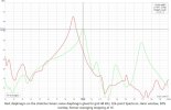
Further tests find that the resonance number I get depends on where the thumper hits the diaphragm and where the mic is picking up the audio. I suspect that what happens is the thumper sends ripples out from the spot where the diaphragm is hit, and when those ripples hit the boundaries of the diaphragm they are reflected back and they travel back and forth for a while until they die out. There are likely standing waves set up and nodes of low output and high output, and the mic picks up whatever it is closest to. Also, when testing the diaphragm on the stretcher the mass and rigidity of the stretcher eliminates some of the higher frequency resonances seen when testing the diaphragm glued to a grid. I suspect some of the higher frequency resonances are from the grid vibrating.
I have a stand that I will adapt to hold the mic and thumper and will position them so that they are always in the same spot relative to the diaphragm when testing.
I have a stand that I will adapt to hold the mic and thumper and will position them so that they are always in the same spot relative to the diaphragm when testing.

mrehorst
Super Member
I glued 4 diaphragms to grids today, setting the resonance on the stretcher at 80 Hz just before sticking the grids down on them. I tested them after gluing the grids and got 90 Hz resonance, a few Hz higher than the factory diaphragms. The resonance will go down a little when I apply the Licron coating, so I'm not concerned about them being a few Hz high. I have a few more diaphragms to glue, maybe tomorrow, and then I can spray them all with the Licron coating.
mrehorst
Super Member
Now I have a new problem. I have two drivers with good factory diaphragms. Do I leave them as-is, or replace them? The part of me that's growing tired of this whole project says leave them alone and finish up faster. The part of me that imagines my frustration a year or two from now, when one or both of those diaphragms fail, says replace them now. I think I'm going to listen to that part of me and replace them now.
The saddest thing is that all the stators on the one speaker seem to be glued well and holding fine. I've carefully inspected and pushed on each of them in a few places and they are solid- so solid it seems likely that I'll end up breaking them if I try to bust them loose so I can reglue them. So I'm leaving them alone and hoping they will stay bonded.
Sigh...
The saddest thing is that all the stators on the one speaker seem to be glued well and holding fine. I've carefully inspected and pushed on each of them in a few places and they are solid- so solid it seems likely that I'll end up breaking them if I try to bust them loose so I can reglue them. So I'm leaving them alone and hoping they will stay bonded.
Sigh...

Thierry
Tape with a passion
It hurt to do it, but I took the two factory original diaphragms off their grids
Can't remember reading it in your posts but did you measure their resonnance before taking them off ? Anyway, you'll have a spanking new pair of ESL63s


WTF~~?
Stupid internet!
I've been rebuilding Stats for 25 years and I just found this thread tonight...
FLOCK~~!
And here I lost my chance to let someone else use my "Patented" Plastic Mylar Stretcher...
Sad face...
Stupid internet!
I've been rebuilding Stats for 25 years and I just found this thread tonight...
FLOCK~~!
And here I lost my chance to let someone else use my "Patented" Plastic Mylar Stretcher...
Sad face...
mrehorst
Super Member
Yes, using the thumper and REW's RTA, positioning the mic at the center of the diaphragm and thumping as close as possible to the center, both read 86 Hz. I stretch the film on my stretcher to 80 Hz and when I glue the grids to the stretched film they end up at 90 Hz (I suspect it's because of a slight difference in the dimensions between the open area of the stretcher and the open area of the grid.Can't remember reading it in your posts but did you measure their resonnance before taking them off ? Anyway, you'll have a spanking new pair of ESL63s
When I'm done, I think they'll be better than new. The tapes and especially the adhesives I'm using on the stators and diaphragms are better than the originals. Especially the cement I am using on the diaphragms. The 4693H contact cement bonds well to both the diaphragm and the grid (which make it a real PITA to have to redo one if I make a mistake in the process).
And here I lost my chance to let someone else use my "Patented" Plastic Mylar Stretcher...
Tell me about your stretcher! Photos please!
mrehorst
Super Member
Speaking of mistakes... I cut a diaphragm on one of the driver grids while attempting to remove some excess glue from its edge with a knife. When I went to put on a new diaphragm, I discovered that I needed to replace some tape on the stretcher, and that I had run out of the Scotch "permanent" double stick tape. Fortunately I had some old Duck brand double stick tape and it actually stuck to the stretcher better than the Scotch stuff. Anyway, diaphragm replaced, and all 8 driver resonances tested before spraying with Licron Crystal. The drivers are drying now and I'll be testing resistivity and resonances again to see if any have changed significantly.
I had a spread in resonances from about 90-96 Hz, but the 96Hz was an outlier with the rest distributed around 92 Hz. This one is what they typically look like:
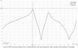
You can see all of them at my blog.
Resonances might drop a little with the added mass of the Licron Crystal coating. Also, I expect that over time, under tension, the diaphragms may relax a bit a drop the resonances further. The factory diaphragms I measured were on the speakers for 40+ years, so maybe they were lower resonance than when they were made. Anyway, I'm not going to fret about the slight differences between the drivers or between them and the factory diaphragms.
I had a spread in resonances from about 90-96 Hz, but the 96Hz was an outlier with the rest distributed around 92 Hz. This one is what they typically look like:
You can see all of them at my blog.
Resonances might drop a little with the added mass of the Licron Crystal coating. Also, I expect that over time, under tension, the diaphragms may relax a bit a drop the resonances further. The factory diaphragms I measured were on the speakers for 40+ years, so maybe they were lower resonance than when they were made. Anyway, I'm not going to fret about the slight differences between the drivers or between them and the factory diaphragms.
mrehorst
Super Member
I tested resistivity and resonance of all the diaphragms with the Licron coating applied. All resistivities were either 10^8 or 10^9 Ohms/square (all good!) and here's driver 31043 resonance to compare with the plot in the post above:
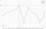
Keeping in mind the resolution of the RTA is 0.7 Hz, it looks like the resonance dropped by about 1 Hz (not unexpected- the Licron adds mass to the diaphragm which should lower resonance).
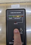
I have uploaded all the resistivity photos and all the resonance plots to the blog page here.
Keeping in mind the resolution of the RTA is 0.7 Hz, it looks like the resonance dropped by about 1 Hz (not unexpected- the Licron adds mass to the diaphragm which should lower resonance).
I have uploaded all the resistivity photos and all the resonance plots to the blog page here.
Last edited:
mrehorst
Super Member
Drivers are reinstalled in the first speaker. Tested first just applying HV bias as I installed them. Complete silence! Once the drivers were all in I hooked up an amp and played some music... perfect! Now I need to install the dust covers and then I'll reassemble the other speaker.
mrehorst
Super Member
I installed one dust cover- I peeled the old one off the frame pieces, mounted VHB tape on it, lightly stretched a piece of film on a granite counter top, put the dust cover frame down and aligned the corners so it was square, then peeled the backing off the tape and stuck it to the film while the frame was resting on the film. Then I cut away the excess and took it to the speaker and tried it. It has wrinkles that I was unable to chase out with a heat gun, but I don't hear it rattling, so I'm not sure I should try redo this one and to do it better on the next one. The frame falls apart until it's stuck to the film, and there's nothing to keep it square until you snap it onto the speaker, so I'm not sure it's possible to do it any better. I'll think about it for a while.
mrehorst
Super Member
The dust covers are the worst part of the design of these speakers. They should have a rigid frame, maybe one that mounts on the assembled drivers/aluminum L channels that can drop in from the top, or maybe each driver should have had its own dust covers. Crazy!
I managed to get dust covers installed on the first speaker in an acceptable way- still with small wrinkles at the corners, but it's not going to be possible to do it any better. That one speaker is finished and playing like new.
I installed the drivers in the other speaker and when I tried to test it by applying bias, discovered that the fuse holder had broken into little pieces. If I manually push down on the fuse the speaker powers up and is silent. I will be getting new fuse holders today and will finish the second speaker.
I managed to get dust covers installed on the first speaker in an acceptable way- still with small wrinkles at the corners, but it's not going to be possible to do it any better. That one speaker is finished and playing like new.
I installed the drivers in the other speaker and when I tried to test it by applying bias, discovered that the fuse holder had broken into little pieces. If I manually push down on the fuse the speaker powers up and is silent. I will be getting new fuse holders today and will finish the second speaker.
mrehorst
Super Member
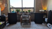
Decided I wanted them tilted up a bit. I designed and printed some feet that tilt the speakers back 5 degrees. I like the sound better, but I'm used to the stage presentation by the 703s with their midrange and tweeters about 18" higher than the center of the ESL-63s. It feels like the sound is coming from someplace lower, and that feels a little unnatural.
The feet are caps that fit into pieces I designed to replace the missing feet from these speakers when I got them. The front and rear feet connect to each other, and there are index bumps inside the sockets so that the foot pieces that get inserted only fit in one direction. That lets me design feet that will tilt the speaker while planting all four feet flat on the floor.
This is one of the foot holders I printed to replace the feet on these speakers. I printed in PETG, on UMMD with a 1 mm nozzle, in 0.5 mm layers.

Here are some flat feet I printed in teal TPU.
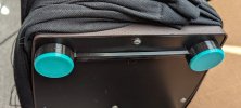
Here are 5 degree tilt back feet I printed- also TPU. I will reprint them when I get some black filament. They are designed so the feet sit flat on the floor even as they tilt the speaker back.
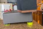
The feet are caps that fit into pieces I designed to replace the missing feet from these speakers when I got them. The front and rear feet connect to each other, and there are index bumps inside the sockets so that the foot pieces that get inserted only fit in one direction. That lets me design feet that will tilt the speaker while planting all four feet flat on the floor.
This is one of the foot holders I printed to replace the feet on these speakers. I printed in PETG, on UMMD with a 1 mm nozzle, in 0.5 mm layers.
Here are some flat feet I printed in teal TPU.
Here are 5 degree tilt back feet I printed- also TPU. I will reprint them when I get some black filament. They are designed so the feet sit flat on the floor even as they tilt the speaker back.
Last edited:

Congratulations and thanks for the great post. I’d love to hear them.
Thierry
Tape with a passion
You may want to use the stands Quad designed for the ESL63s, I find they bring great improvement in prsentation and sound. As I had a hard time to find a pair in good condition and at a reasonable price I decided to replicate them :Decided I wanted them tilted up a bit. I designed and printed some feet that tilt the speakers back 5 degrees. I like the sound better, but I'm used to the stage presentation by the 703s with their midrange and tweeters about 18" higher than the center of the ESL-63s. It feels like the sound is coming from someplace lower, and that feels a little unnatural.
The feet are caps that fit into pieces I designed to replace the missing feet from these speakers when I got them. The front and rear feet connect to each other, and there are index bumps inside the sockets so that the foot pieces that get inserted only fit in one direction. That lets me design feet that will tilt the speaker while planting all four feet flat on the floor.
This is one of the foot holders I printed to replace the feet on these speakers. I printed in PETG, on UMMD with a 1 mm nozzle, in 0.5 mm layers.
Here are some flat feet I printed in teal TPU.
Here are 5 degree tilt back feet I printed- also TPU. I will reprint them when I get some black filament. They are designed so the feet sit flat on the floor even as they tilt the speaker back.