• The move to the new server is done. There are some software and database maintenance updates in process. This has us passing the hat around to help out. We appreciate any donations. Seriously, even a dollar helps. The payment page may be found here - https://www.audiokarma.org/support.html

Rare Holy Grail Frazier Model Elevens

I just have not found out if it was because no 5 uf was in stock or if it had a positive effect to the sound.
A couple of thoughts.

I've read that in some circuits capacitors were series stacked to increase the voltage rating when higher voltage caps were either unavailable or cost prohibitive.

I have also read that in many electrolytics, particularly of older manufacture, the actual capacitance value drifts significantly as you approach the working voltage limit.

So, my thought is "did Frazier stack those caps to create a more stable filter given the nature of these speakers and the liklihood that they would be driven from significantly large amplifiers?"
 
A couple of thoughts.

I've read that in some circuits capacitors were series stacked to increase the voltage rating when higher voltage caps were either unavailable or cost prohibitive.

I have also read that in many electrolytics, particularly of older manufacture, the actual capacitance value drifts significantly as you approach the working voltage limit.

So, my thought is "did Frazier stack those caps to create a more stable filter given the nature of these speakers and the liklihood that they would be driven from significantly large amplifiers?"

Good question, If I find that all known existing model 11's had two 10 uf caps in series, it would tell me they intended to do this for the design and testing results.
 
Last edited:
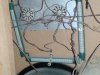
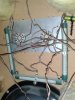
Took some pictures of the #166 serial number, looks like it was assembled by a different person, no initials or date inside. It seems to be the same except for the tube type coils inside, this one has three instead of two. Caps are done the same, 4 12's in paralell, and two 10uf in series. Drivers are the same in both speakers.
 

Attachments

  • 002.jpg
    002.jpg
    57.4 KB · Views: 158
  • 005.jpg
    005.jpg
    72.8 KB · Views: 148
  • 007.jpg
    007.jpg
    73.7 KB · Views: 121
  • 006.jpg
    006.jpg
    69.1 KB · Views: 146
  • 008.jpg
    008.jpg
    61.2 KB · Views: 128
Took some pictures of the #166 serial number, looks like it was assembled by a different person, no initials or date inside. It seems to be the same except for the tube type coils inside, this one has three instead of two. Caps are done the same, 4 12's in paralell, and two 10uf in series. Drivers are the same in both speakers.

Steve. Looking at the x-over pics again, I don't think those long wire wound "things" are inductors. They are most likely variable resistors. If you notice the layout in #166, you see the "clamps" holding the tube on has an indent on it.

This would give the ability to fine tune the amount of resistance in the circuit. I have no idea why one used 2, and the other used 3. I DID forget to mention about doubling the power for series caps. I meant to. Brain Fart on my part. :D

I would love to see the x-over drawn out. If it is a series x-over, that might explain alot of how the x-over is built.

The mystery continues. :scratch2:
 
Steve. Looking at the x-over pics again, I don't think those long wire wound "things" are inductors. They are most likely variable resistors. If you notice the layout in #166, you see the "clamps" holding the tube on has an indent on it.

This would give the ability to fine tune the amount of resistance in the circuit. I have no idea why one used 2, and the other used 3. I DID forget to mention about doubling the power for series caps. I meant to. Brain Fart on my part. :D

I would love to see the x-over drawn out. If it is a series x-over, that might explain alot of how the x-over is built.

The mystery continues. :scratch2:


The two tube resisters are longer than the three, so they must of used an extra one to get the same result using shorter lengths. It's not your average crossover that we are used to seeing, I love a good mystery, so long as it is solved. :D
 
Those are big brutes for sure and have a huge footprint. For the money more than likely the score of 2014 and I thought getting my '87 Polk Audio SDA 2Bs for $50 was the score or 2013. A question for the Frazier group out there. A friend of mine had what were were simply called Frazier Black Boxes and sounded great but then he traded them in for Dalhquist 10s. In the Frazier family what wrung on the ladder did they reach? Great score as you know already.
 
I knew there was something special about series caps, and it was the additive voltage rating. I ran into an old radio guy once who would install series caps in the power line to drop high modern voltage down to 110V for his old radios. He would use low voltage caps (like 100V) and would argue that they added up to enough of a voltage rating to do the job.

I would think there should be an effect on phasing though. With an AC signal charging and discharging the caps at a rapid rate, it seems like two caps charging and discharging in series would not act like a single cap. But again, I'm rusty on this stuff.

We really really need a schematic of this beast! What are those big multiple terminal things? I'm guessing discrete attenuator switches for the mids and tweeters. They sure planned to dissipate some serious heat with those huge power resistors. I don't see any inductors either, so this is a VERY simple crossover.
 
Well, that explains it. From the pics, it's hard to get a an indication of size.

Too bad Zilch isn't still with us. He could probably just look at them, and figure it out.

Man, I wish I was closer to you. I would love to see them.

Map out the x-over and post it. Somebody will come along and tell you what's what.

You have the caps, or have to order them?
 
Even if you can draw a picture of everything just as it lies (i.e. a wiring diagram), we can translate it to a standard schematic layout. You've piqued our curiosity now.
 
I ordered four 10uf's and two 4.7uf caps, along with the eight 12uf's, we are bound to figure out which I should use. I don't want to change anything that Jack Frazier did if it was for the purpose of sound improvement. I will try to get time to make a map of the crossover, it most certainly needs to be done since I don't think anything is on the web about the crossovers. Fun stuff! Thanks a bunch for everyones help and interest, I know they are not the best sounding or going to set the world on fire, but you can't help but like the history, and the whole Frazier story. :thmbsp:
 
I know they are not the best sounding
I wouldn't be to hasty to judge that. Get them on the right combination of amplifier and upstream gear and they might surprise.

An EVM-15B in that size box is going to play quite low with a great deal of authority. Not a bad thing in my world. :D
 
I wouldn't be to hasty to judge that. Get them on the right combination of amplifier and upstream gear and they might surprise.

An EVM-15B in that size box is going to play quite low with a great deal of authority. Not a bad thing in my world. :D

I just didn't want everyone to get the idea that I think they are anything more than what they are. They do very well so far, not so good on digital tracks from my ipod, seem to be very picky on what source I use. I have yet to try vinyl, CD's sound much better than my ipod. You have to remember, I have JBL L220's and ADS L1590's here, well you can get the idea from my signature. These probably will be one of the loudest though. :D

Oh yeah, most certainly the heaviest! :yes:
 
Do you have a multimeter? If you can measure the resistance on those coil resistors, it would help document the crossover. They are probably not marked but they might be.
 
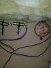
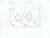
This is the best I could do for tracing the crossover, the three resisters I did not show where they connect because they just go to the pots. If I was to draw them it it is just too many lines, they are just to attenuate the mids and highs. I'm surprised to see the 15 inch woofer ground going to a the mid pot, it must mean the 15" woofer carries some midrange. My head is spinning right now. :confused:

I deleted this one because it had mistakes.
 
Last edited:
Crazy stuff.
 

Attachments

  • 022.jpg
    022.jpg
    83.1 KB · Views: 123
  • 023.jpg
    023.jpg
    69.7 KB · Views: 80
  • 024.jpg
    024.jpg
    78.8 KB · Views: 84
The flagship of the DOMINATOR line!!!

All that's missing is the red light tweeters:
https://www.youtube.com/watch?v=mNzr6lfiHJE

Only kidding... I only got to hear these once as a kid, at B&M electronics in the Montrose district. The 1st ELP album had just come out and they fired up Lucky Man on reel-to-reel and those Fraziers blew me away.
 
This is the hinkiest crossover I've ever seen, to the point where I've dropped what I'm supposed to be doing to figure it out.

We'll need the connections for those resistors though, can you map out the pins on the 'pots' and draw them in? Are those actually pots or multiposition switches?

I'm working on a diagram which I will post for everyone to look at and verify. Hopefully once we get it right, someone smarter than me can explain how this damn thing works. There are drivers wired out of phase (which isn't unusual), drivers operating full range, all kinds of stuff.
 
This is the hinkiest crossover I've ever seen, to the point where I've dropped what I'm supposed to be doing to figure it out.

We'll need the connections for those resistors though, can you map out the pins on the 'pots' and draw them in? Are those actually pots or multiposition switches?

I'm working on a diagram which I will post for everyone to look at and verify. Hopefully once we get it right, someone smarter than me can explain how this damn thing works. There are drivers wired out of phase (which isn't unusual), drivers operating full range, all kinds of stuff.

My head is twice the size it was, wow, what a mind bender getting it on paper.
 

Attachments

  • model 11 pots0001.jpg
    model 11 pots0001.jpg
    36.2 KB · Views: 147
I'm having trouble posting a pic right now, but here's what I have. Both the tweeter and the mid don't seem to connect to the negative input (Input-). And, from Input+, after going through the 5 uf cap and the .318 coil, all input then goes directly back to Input-. Something is wrong with my interpretation, or your drawing. :scratch2:

It is probably still a hinky crossover but I think the hink has a kink! Check it out and verify when you have time. :thmbsp:
 
Back
Top Bottom