• The move to the new server is done. There are some software and database maintenance updates in process. This has us passing the hat around to help out. We appreciate any donations. Seriously, even a dollar helps. The payment page may be found here - https://www.audiokarma.org/support.html

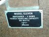
Rare Holy Grail Frazier Model Elevens

Ooops, cross post..hang on while I read your last.

Edit: OK, you got the switch layout, great. Can you verify the first drawing? It's possible I just do not understand how this damn thing works!
 
Those are nice tubular ceramic wirewound tapped resistors, the resistance wire has large gaps. Those where very popular in Ham and Civil Defense HF transmitters in the 1950's. You are not going to have the problem with shorted windings like we find in those old transmitters' tightly wound examples. Should you have to replace one Ohmite still makes them.
 
Those are nice tubular ceramic wirewound tapped resistors, the resistance wire has large gaps. Those where very popular in Ham and Civil Defense HF transmitters in the 1950's. You are not going to have the problem with shorted windings like we find in those old transmitters' tightly wound examples. Should you have to replace one Ohmite still makes them.

That's nice to know, I have never seen them in a crossover before.
 
The thing you want to do first off with those tapped resistors is record their resistance settings. I would actually write that value near each resistor. With this known if you have to replace one just clip your test lead on one end of the new resistor then with the other probe tap down the wire until you get to where your recorded resistance is located on the open area. When you move the tap to that area loosen it enough so you can rotate it to the sealed portion on each side of the open wire this opens it enough so there is a gap over the conductive wire, you want to slide the tap on the conductive area as little as possible.
 
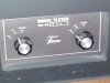
These are not pots but selector switches, three setting each, flat, -3db, and -6db

OK, good to know. I can't tell from the pics at this resolution, how do the contacts actually move for the 3 settings? Does the switch connect the two terminals opposite each other?
 
OK, good to know. I can't tell from the pics at this resolution, how do the contacts actually move for the 3 settings? Does the switch connect the two terminals opposite each other?

I'm not sure how they work for certain. But there are two lugs on the side that are across from eachother, the other tabs are located around the back edge.
 

Attachments

  • 025.jpg
    025.jpg
    90.1 KB · Views: 103
  • 012.jpg
    012.jpg
    46.9 KB · Views: 110
  • 027.jpg
    027.jpg
    54.8 KB · Views: 105
  • 028.jpg
    028.jpg
    108.4 KB · Views: 101
About the time I think I have seen all that is Frazier.....along comes another one better than the one before!!
Cobgrats on those for sure!
DC
 
About the time I think I have seen all that is Frazier.....along comes another one better than the one before!!
Cobgrats on those for sure!
DC

Thanks DC, Now I have them hooked to my Yamaha surround receiver as fronts, no sub needed with these, man they make it feel like were having an earth quake.
 
Last edited:
Mil-spec ceramic rotary switches. Wow.

The specification sheet says they were built without any regard for cost, and that they used a two way system in paralell. I guess the tweeters were considered good stuff back then. :D

**Crossover**
Two series type - 12db per octave utilizing high grade polycarbonate and metalized mylar condensors, air core inductors, specially designed and individually bridged for low insertion loss and smooth transition between components.

So they are saying that the capacitors are good ones, it's possible that they are all in spec and do not need changing. :scratch2:
 
Excellent find! This thread is getting good, is there more of a back story to these? Who owned them? One owner? Downsizing?
 
Excellent find! This thread is getting good, is there more of a back story to these? Who owned them? One owner? Downsizing?

The person that owned them passed away about 6 weeks ago, his best friend was helping get rid of anything left in the estate. His friend (Mark) said nobody wanted the huge speakers, nobody new anything about them other than the owner had them the whole time he lived in Ft. Lauderdale (25 years). He lived in NY before coming to Florida, his friend believes that they came from NY with him. That is all the information I could get on them.
 
Last edited:
I'm having trouble posting a pic right now, but here's what I have. Both the tweeter and the mid don't seem to connect to the negative input (Input-). And, from Input+, after going through the 5 uf cap and the .318 coil, all input then goes directly back to Input-. Something is wrong with my interpretation, or your drawing. :scratch2:

It is probably still a hinky crossover but I think the hink has a kink! Check it out and verify when you have time. :thmbsp:

I get dizzy trying to figure it out, between my rookie diagram and all those wires in the cabinet, I just get lost. :stupid: :scratch2:
 
It's really interesting putting the ear up to each driver area, the big 15 " woofer is running more like a full range or maybe midwoofer, the 12" woofer is all bottom end, the four mids have a very subtle mid sound, and the tweets carry the sizzle with a little midrange. I'm not sure how they did it, but you get a very balanced sound stage.
 
More cool information supplied by the Frazier users group, price sheet showing what the Fraziers were sold for in 1981.
 

Attachments

  • Frazier price list.jpg
    Frazier price list.jpg
    37.2 KB · Views: 126
Crossover recap

I just recieved my new Dayton 5% capacitors, I have the option of replacing the two 10uf ones that are in series with one 4.7 uf, or I have new 10uf ones to put in series, and put things back to exact from factory.

I can not get any information as to why exactly the two 10's were used in series, it has been suggested that they used what they had, but there is a possibility that this design added something to the crossover that Jack Frazier thought necessary. If these speakers were touted as no expense was too much, you would think they could of easily ordered the correct capacitors for their needs. I would just like to get as much advice and expertise about this before making a choice. I would prefer to do this one time and not experiment. Any help in this matter will be appreciated. :thmbsp:
 

Attachments

  • 001.jpg
    001.jpg
    101.5 KB · Views: 63
Since you have them, there's certainly no harm in putting the 10's in there. The 4.7 would be off a bit anyway (only 6% assuming all the caps are spot on, which they never are). In view of the comment above about the quality of parts, definitely remove the old ones carefully and save them. If you have a meter that will test caps, it would be interesting to see how they measure out. And if you can do that, you can also mix and match up the new 10's to get values for each speaker that are the closest to each other.

If you want to verify your crossover drawing while the speaker is open for the cap replacement, one way you can do that is just to trace from + and - on each driver back toward the inputs and verify that everything is connected in the order shown on the drawings. Wouldn't hurt to add in the switches and wiring also. Or, if you can get more pics showing all the wiring, we might be able to tease it out from the photos. Right now the photos are from too far away to be useful for that. It's mainly for documentation purposes since there is nothing on the net on these, so it's up to you how much time you want to put into it. But I'd be willing to take another crack at a schematic given some more info to work with. Just in the name of science. :D
 
Since you have them, there's certainly no harm in putting the 10's in there. The 4.7 would be off a bit anyway (only 6% assuming all the caps are spot on, which they never are). In view of the comment above about the quality of parts, definitely remove the old ones carefully and save them. If you have a meter that will test caps, it would be interesting to see how they measure out. And if you can do that, you can also mix and match up the new 10's to get values for each speaker that are the closest to each other.

If you want to verify your crossover drawing while the speaker is open for the cap replacement, one way you can do that is just to trace from + and - on each driver back toward the inputs and verify that everything is connected in the order shown on the drawings. Wouldn't hurt to add in the switches and wiring also. Or, if you can get more pics showing all the wiring, we might be able to tease it out from the photos. Right now the photos are from too far away to be useful for that. It's mainly for documentation purposes since there is nothing on the net on these, so it's up to you how much time you want to put into it. But I'd be willing to take another crack at a schematic given some more info to work with. Just in the name of science. :D


Since Fraziers seem to be well liked, and admired, it just makes sense for me to do as much documentation, and research as possible. These were Jack Fraziers top designs for home use, if I can help provide missing information on them I really would like to do that. It can only help others that might find more 11's in the future, along with informing current model 11 owners.

I know enough about crossovers to get by, but it is a challenge to try and understand these. If these were his prize models, and they advertised no cost was too high in their design, I have to lean towards supply as reason for some of these odd combinations. It is possible that the supplier that had the brand of cap he disired, did not carry a 5 uf cap? There are other combinations that make more sense than putting 10's in series though. The question is there, why 2 10's in series over a 3uf and 2uf in paralell? I can't help but want to know, just my nature I guess. It is the easiest to assume they used what was in stock, but I have not found that any other 11's had it done another way.
 
Back
Top Bottom