• The move to the new server is done. There are some software and database maintenance updates in process. This has us passing the hat around to help out. We appreciate any donations. Seriously, even a dollar helps. The payment page may be found here - https://www.audiokarma.org/support.html

RCA SP-10 Restoration

elpulpo88

Inveterate tinkerer
So recently I’ve been falling further down the rabbit hole of vintage hifi. What a tragedy! I’ve been hooked on the sound of simple, high efficiency speakers, idler drive turntables, and tube based electronics. My main amp for a while has been a Primaluna Dialogue, but I’ve been hunting for some vintage monoblocks.

the other day I came across a listing for a really clean pair of RCA SP-10 amplifiers. What little I could find on these amps got me very interested: designed by Harry Olson’s team in Camden, overbuilt transformers, 1/2% tolerance parts in the signal path. These were originally designed to mate with the SL-12 drivers, with the famed LC-1A matching the SP-20 amps. I knew they wouldn’t last long, and I knew my chances of finding a clean pair again were slim to none, so I jumped on them.

Naturally something this rare and obscure is going to require some attention before they can be powered up, and at the minimum will need a power supply recap. I’ve been going over the photofact, and studying the current state of the pair. One is entirely stock, down to the magenta QC marks on each solder joint, the other has a couple signal caps that have been replaced. I’m trying to decide how to proceed with the power supply caps, since neither CE nor Hayseed produce can caps of the right value. I’m leaning towards bypassing the cans, but leaving them in place for looks. I’m curious if there is any opinion out there on what type or brand of modern capacitor is the best option for retaining the original sound of such an amp with paper can caps. Or does it matter significantly less with the caps in the power supply versus those in the signal path? Luckily my dad is an ace amp builder and tube guy, so I have some fantastic in-house support, but am always curious to crowdsource information from guys who may have experience with these particular pieces.

I’ll try to keep this thread updated with pictures and findings along the way, and am really excited to get these puppies singing again. Thanks in advance for all opinions, solicited and otherwise!

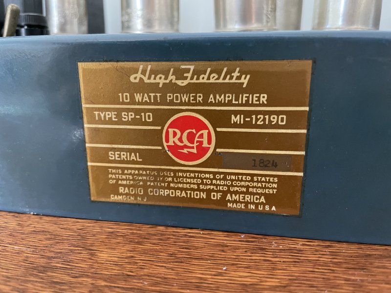
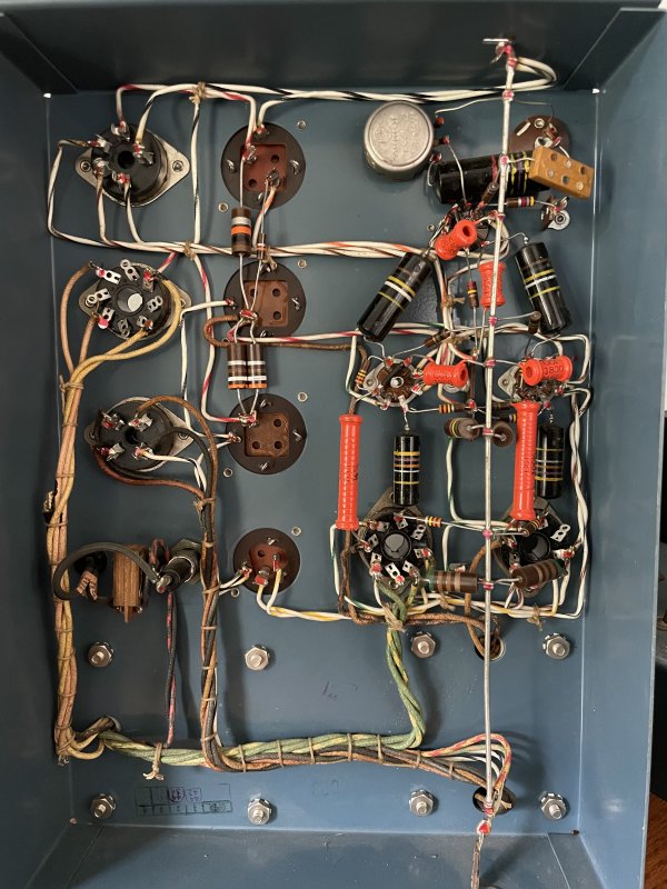
 
Register to hide this ad
What little I could find on these amps got me very interested: designed by Harry Olson’s team in Camden, overbuilt transformers, 1/2% tolerance parts in the signal path. . . . Naturally something this rare and obscure is going to require some attention before they can be powered up, and at the minimum will need a power supply recap. . . . I’m trying to decide how to proceed with the power supply caps, since neither CE nor Hayseed produce can caps of the right value. I’m leaning towards bypassing the cans, but leaving them in place for looks. I’m curious if there is any opinion out there on what type or brand of modern capacitor is the best option for retaining the original sound of such an amp with paper can caps. Or does it matter significantly less with the caps in the power supply versus those in the signal path?
Cool amps and certainly not easy to find, I'm sure. I'm not sure if some of the info you found on this is accurate, though.

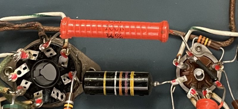
As far as I know there were no parts back then (resistors and caps) that had a 0.5% tolerance. The tightest tolerance on those carbon comp resistors was 5% and it looks like that's what you have in the pic if the 4th color band is gold. Silver would be 10% and no band is 20%.

It's entirely possible, however, that the individual parts were all measured and that they hand picked parts that were within 0.5% of the correct value.

Carbon comps are not particularly stable. Their values tend to drift higher due to age, humidity and heat. Even if they still measure in spec they can be noisy.

The can caps are electrolytics, not paper. I forget if the Bumblebee caps are paper or mylar construction but, as mentioned, they are almost always leaky (electrically) and should definitely be replaced.

As mentioned, Hayseed will stuff cans with whatever values you like and they use high quality caps but they're not cheap. I would avoid any other replacement cans even if you happen to find some that are the correct values.

You could also just disconnect the cans, leave them in place for looks and mount individual caps underneath. That will be much cheaper. I try to use caps that are rated for 8,000 to 10,000 hours at 105 degrees. Their other specs tend to be excellent too. But most any modern cap should be higher quality than the originals. Use name brand caps only (Nichicon, Panasonic, United Chemi-Con, etc) sourced from a major supplier like Mouser or Digi-Key. That's the best way to avoid counterfeits. Digi-Key has a free shipping option:

http://www.audiokarma.org/forums/in...hipping-on-parts-orders.739513/#post-10018562

I looked at the schematic and, at first glance, the use of an 80uf first cap after the 5Y3GT rectifier looks too high. The 5Y3 data sheet says maximum is only 20uf. However, since these are mono amps the current draw is much less than if the 5Y3 was supplying both channels.

There are 3 charts for cap input on the data sheet and the amp must pass all three of these tests. A quick look at them based on the what's in the schematic suggests that 80uf might be OK. You should go through the graphs more carefully, however, to confirm that.
 

Attachments

At 4 cans per chassis the haysed and CE are going to add up quickly...
You'll easily have 2-3 Benjamin's in the electrolytic caps for the stereo pair...
That being said, you have 2 absolutely stunning survivors. They are gorgeous and scabbing in electrolytic caps under the chassis is absolutely the the Mickey Mouse way to go.
What I'm trying to say is that these gorgeous amplifiers are totally worth the expense to source propper cans for, even if it means parallel sections or calling in a custom build...
Worth it.
 
Beautiful amps - those are what dreams are made of!

If you're planning to use then, the bumblebees will need to retire, and I support the idea to change the electrolytic cans too.

Getting some good quality radial capacitors under the chassis on terminal strips should be well within your Dad's skill set

I'd leave the resistors alone unless one is noisy or else if the phase inverter is badly unbalanced.
 
Last edited:
What a find! You are a lucky fellow indeed. Those amps are definitely worth the bother and expense of new PS caps and, as others have noted, the Bumblebee caps are likely leaking and will need replacement as well. The real challenge will be finding coupling caps with a similar sound signature as the Bumblebees but without their reliability problems. I wish I had a recommendation for such a cap but unfortunately I don’t.
 
Really appreciate all the input so far. The bumblebees definitely have to go, and again, I’m super lucky to have a dad who’s been scrounging for decades, and has a lot of good options for coupling caps. It’s helped by the fact that the circuit is fairly conservative, so he has some options in mind that normally are hard to implement in typical tube circuits.

Cool amps and certainly not easy to find, I'm sure. I'm not sure if some of the info you found on this is accurate, though.

As far as I know there were no parts back then (resistors and caps) that had a 0.5% tolerance. The tightest tolerance on those carbon comp resistors was 5% and it looks like that's what you have in the pic if the 4th color band is gold. Silver would be 10% and no band is 20%.

It's entirely possible, however, that the individual parts were all measured and that they hand picked parts that were within 0.5% of the correct value.

You are right on the money about the carbon comps and the bumblebees, all 5% parts. But the orange wire wound resistors are indeed stamped with 1/2%. I was shocked when I saw that.


What a find! You are a lucky fellow indeed. Those amps are definitely worth the bother and expense of new PS caps and, as others have noted, the Bumblebee caps are likely leaking and will need replacement as well. The real challenge will be finding coupling caps with a similar sound signature as the Bumblebees but without their reliability problems. I wish I had a recommendation for such a cap but unfortunately I don’t.

Like I said, I will be working hard on getting this piece right. We are going to audition several options for coupling caps before anything gets soldered in. Right now some potentials he mentioned are black beauties, sprague vitamin Q, and some other PIO options.

Very nice!!! congrats on your acquisition. What is the tube compliment? are the serial numbers consecutive?

Serials are not consecutive, and they definitely have lived different lives. One is immaculate, the other is a little more worn, but all the lettering looks great, and not a bit of rust. They use a 12AU7, two 6AU6 drivers, and two P-P 6V6GT. Rectifier is a 5Y3GT. Tubed more like a guitar amp, honestly, but run very conservatively. B+ is only 325V.
 
You are right on the money about the carbon comps and the bumblebees, all 5% parts. But the orange wire wound resistors are indeed stamped with 1/2%. I was shocked when I saw that.

We are going to audition several options for coupling caps before anything gets soldered in. Right now some potentials he mentioned are black beauties, sprague vitamin Q, and some other PIO options.

They use a 12AU7, two 6AU6 drivers, and two P-P 6V6GT. Rectifier is a 5Y3GT. Tubed more like a guitar amp, honestly, but run very conservatively. B+ is only 325V.
Yeah, wirewounds are different and apparently much easier to manufacture to close tolerances. Unless they've been overheated by some catastrophic event they don't need to be replaced.

Perhaps others will comment, but I'm not so sure "black beauties" are any more reliable than the bumblebees.

As you say, the circuit itself doesn't seem to be anything exotic. It's the output transformers that are the stars of the show. For anyone who's interested in the details, here's the Sams in pdf which can be enlarged to show detail.
 

Attachments

I'd also suggest that you let pops keep his "tone cap" collection complete.
Modern film caps will be substantially better and you can do each amp for about $20 if you buy them from Mouser.
If you have a vintage cap short out (and they love to short out) the tube you render useless is going to cost more than $20...
Film caps are cheap insurance.
 
Any relation to our member PakProtector? He just made reference to one of these in my thread. He may have some interesting input to your's.

Don't know about relations, but this amplifier is unusual because of the negative feedback arrangement, and is often cited on the forum and by others interested in amplifier design. Usually though most people know it as the 10 Watt amplifier in the back of the RCA tube manual. To have a real set of originals is something very very precious to a person interested in the history of tube amplifier design. What makes it noteworthy is the high amount of negative feedback used between the 6V6 and the 6AU6, and zero negative feedback around the output transformer. This allows excellent performance from the output stage while not involving the transformer and its associated nasties in the feedback loop at all. They should sound fantastic when restored.
 
You could look at it that way or you could say it just simplifies the DIYness by ignoring the OPT transformer contribution of total distortion, because it skirts the necessary fudgement for different OPT's that might be used from builder to builder, RCA not wanting to complicate the amp, not because it is a better method of implementing FB for total distortion and FR benefit.

Whatever was the original intention, back when this was just an economical way to make 10W, is lost to time, but it has been my experience that this type of design sounds better than it has any right to. Also, note the SP-10 itself was not a DIY product, but was RCA's attempt to have a presence in the growing hi-fi market, and that this design is definitely deliberate, because it would have been cheaper to use loop feedback and one less tube.
 
There's plenty of room underneath to acommodate individual caps leaving the cans in place.
I will suggest grounding replacement caps to the same chassis or buss locations as the caps they replace.
There is a pair of 2w 390 Ω resistors in parallel which could probably be replaced by a single 4-5w 195 Ω metal oxide resistor
 

Attachments

  • IMG_1784.JPG
    IMG_1784.JPG
    141.7 KB · Views: 68
Any relation to our member PakProtector? He just made reference to one of these in my thread. He may have some interesting input to your's.

No relation, but interesting that he brought it up. The circuit design analysis is above my pay grade, but I have seen mention that these do use serious OPT’s, I saw someone say they, or those in the SP-20 were the same units from a 200W theater amp that was being produced at the time. I haven’t been able to find any specs or stamps on them to verify this, just going off apocryphal rumors at this point.
 
These sound really, really good. I got turned on to one nearly 20 years ago. The only thing I would do to them is get rid of the 12AU7. 6CG7 at the same operating points WILL sound better. recall that that tube is outside the FB loop... :)

I have to say that, I know they would sound good, and I would still want to work on them. Built around an S-265-Q, and with an instrumentation pentode instead of the 6AU6 would be where I'd start. And given how good an E-Linear amp built with a 6AU6 front end sounded, it just might not be much improvement...LOL I like the chance to engineer an improvement built around a different set of compromises, generally these involve build cost componentry and wasting power/heat to get a better operating point. The SP10/20 will serve as a reference in any case. Eclipse one and you can count yourself accomplished.
cheers,
Douglas
 
Very nice amps! I'd love to have a set of the originals. As is I'm on my second "from scratch DIY" build. (my son loved it so much I had to build another)
Best sounding amp (in my limited experience) that I've heard.

If I can figure out how to add images I'll post a thread with the build if anyone is interested.
 
Time for an update, the amps are just about back in business.

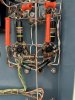
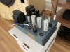
Though I may be flamed for Mickey Mouse behavior by some, I decided to recap the power supply underneath the chassis. That way I could retain the original Aluminum can caps for looks up top, and it also proved impossible to find suitable replacements from the vendors for any kind of reasonable price, and since some of the phenolic washers on the caps had been snapped prior to when I got the amps, I would need to refasten the replacements with screws, much as I’d like to be able to rivet the replacements. Using those screws, my dad and I built some new power supply eyelet boards with garolite, and used standoffs to secure it beneath the original can caps. I used Sprague Atoms for the power supply, and Kiwame carbon film resistors to replace the original carbon comps. I also was able to wire the replacement cathode bypass caps directly to the ground bus from the power tube sockets by not using the original can cap location.

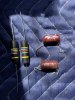
Once the power supply was done, I changed out the .047 coupling caps in both amps. This was necessitated by one amp came to me with some suspect no-name replacements for the original bumblebees, and I want the two amps to match, parts-wise. Since Jupiter makes reproduction Bumblebees in that value, I put a couple of those in each amp. At this point, I checked for shorts and checked the ESR on the remaining 3 Bumblebees in each amp, and finding them to be all right, powered up each amp slowly with a variac, and checked voltages. Everything looked good, and when I put some music through them, music came out the other end!

First impressions are that these amps really live up to their reputation. Amazing sound from an unassuming looking amp. They drive my Altec based speakers easily, with plenty of bass heft. Midrange is super transparent, and driving, in particular I’ve been struck by how immediate and quick these amps sound. The audiophile term “PRaT” comes to mind.

I have noticed some very light distortion or grain on certain peaks, and only on recordings with a fairly good amount of dynamic range. I don’t always notice it, which has me questioning whether some of it is in the recordings themselves. One amp has a very small amount of low level hum that would be nice to eliminate, but it’s not noticeable at the listening position. Overall though, I’m super happy with the outcome of this project, and they may just sound better than my current reference amp, a Primaluna Dialogue integrated. I’ll have to listen a bit more to be sure.

In terms of remaining work, I’m planning to bypass the input sensitivity potentiometer, and set them for 0.7v using a 91k resistor instead. Lastly, I am considering whether or not to try other caps in place of the Bumblebees that were retained, the .47 input cap, and the .1 coupling caps between the 12AU7 and the 6AU6 tubes. I am thinking Jupiter’s copper and wax could be a strong option, since they don’t make the right value Bumblebees, and new caps would eliminate any lingering concern about the old parts continuing reliability.

This was my first real foray into rebuilding old tube gear, rather than just appreciating it once rebuilt by others. It certainly makes me appreciate it to a whole different degree, and now I am itching to build more. I’m tempted to try a scratch built single ended 2A3 or 300B circuit down the line, and already am working on a passive preamp to go with these amps, based around an intact audio autoformer. Never any shortage of projects around here!

CE84E30F-0B1C-458A-8477-1919D7EBF74B.jpeg 532FEFFD-4669-4C91-A9F0-C7CABAA79F63.jpeg 55D22DC6-B9FF-4BD8-A025-92E318896D60.jpeg 76421EDC-3378-4CD0-AFAD-5D274920B5DE.jpeg 65F3D567-C795-4720-BA57-16814447EC15.jpeg FA34B015-944E-48BD-9A57-BADD7ABA242D.jpeg 4EFEFED4-5E24-4AED-ADEC-A0C92DBC6691.jpeg
 
Back
Top Bottom