• The move to the new server is done. There are some software and database maintenance updates in process. This has us passing the hat around to help out. We appreciate any donations. Seriously, even a dollar helps. The payment page may be found here - https://www.audiokarma.org/support.html

RCA SP-10 Restoration

I have been wavering on 'upgrading' the 6AU6 driver stage. Examine the Altec 260 amplifier circuit. That puppy runs type 813 finals( as pentodes) and feeds them with 6AU6's... :)

The 6AU6 are fed from a rather neat input transformer. That amplifier is pretty simple.

Here is a clean copy of the schematic. The 6AU6 are not only loaded by the 813 grids but a grid choke bypassed with 180k plate loads. That is a pretty steep load for a 6AU6 with 150kOhm plate loads. Half a percent THD up to ~200W with a 1kHz signal. I have no doubt this would be significantly lower( the power output ) if done at 30 Hz...let alone 20 Hz... :)

Douglas
 
Last edited:
I have been wavering on 'upgrading' the 6AU6 driver stage. Examine the Altec 260 amplifier circuit. That puppy runs type 813 finals( as pentodes) and feeds them with 6AU6's... :)

The 6AU6 are fed from a rather neat input transformer. That amplifier is pretty simple.

Here is a clean copy of the schematic. The 6AU6 are not only loaded by the 813 grids but a grid choke bypassed with 180k plate loads. That is a pretty steep load for a 6AU6 with 150kOhm plate loads. Half a percent THD up to ~200W with a 1kHz signal. I have no doubt this would be significantly lower( the power output ) if done at 30 Hz...let alone 20 Hz... :)

Douglas

What a cool and at the same time terrifying amplifier! Very neat that Altec used the 6AU6 as drivers for such large output tubes
 
What a cool and at the same time terrifying amplifier! Very neat that Altec used the 6AU6 as drivers for such large output tubes
I don't quite get it. That is a 540V B+ to that stage, rectified by an 'instant on' 5R4GY. IOW, 6AU6 are made from stern stuff. My pair of W6m run 6V6GTA for the E-Linear front end. I would have thought nothing less would do for such a beast as the 260A... :)

Douglas
 
I don't quite get it. That is a 540V B+ to that stage, rectified by an 'instant on' 5R4GY. IOW, 6AU6 are made from stern stuff. My pair of W6m run 6V6GTA for the E-Linear front end. I would have thought nothing less would do for such a beast as the 260A... :)

Douglas

You know, there's the 600V coupling capacitors which have 540V on one side and -100V on the other before the tubes fully warm up. There's the limited ratings of the 6AU6. There's the insane 1800V plate voltage on the outputs, and then there's the 0.5% distortion at anything above 10W at 1kHz. I think your W6Ms are just better designed amplifiers, these Altecs are both scary and a little careless looking. Just cause you can doesn't mean you should, I'm surprised Altec wasn't a little more conservative with this design.
 
There are a couple of popular designs that don't quite seem right just by the book ratings. The 12ax7 driving the output tubes in most Mac amps doesn't really seem like they lead an easy life, yet you don't hear of a lot of problems with those. I get that its probably not running very much current but thats a lot of voltage difference in a wee little package.

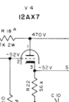
These are running voltages in an MC40, at turn-on it will be even more of a voltage difference until things get going.

1729124036535.png
 
Do you all think the 6AU6 in this circuit could provide enough voltage swing to drive a 6HJ5 or 6HD5?
(I'm guessing around 50v, control grid to cathode, on the 6HJ5 or 6HD5.)
 
I would guess that your 50V would be peak to peak. That shouldn't be too hard for the driver stage but as designed the SP-10 shows a cathode voltage of 20V so 40V p-p is required to drive it. The 6HD5 doesn't look like it will require too much more, if any.
 
At what operating point? I looked at the plate curves from the Raytheon data sheet and guessed that you would probably be somewhere in the -25V range for grid bias which would require about twice that much voltage drive assuming you stay in AB1. You will need to tell us your intended op point which will then drive out the grid bias voltage.
 
At what operating point? I looked at the plate curves from the Raytheon data sheet and guessed that you would probably be somewhere in the -25V range for grid bias which would require about twice that much voltage drive assuming you stay in AB1. You will need to tell us your intended op point which will then drive out the grid bias voltage.
Yup. You're right. It's around -25v. I did an arithmetic goof. I'm looking at 4k plate-to-plate and 320v on the plates.
 
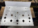
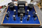
I've begun some work on my stereo version of the SP-10. Got the top plate drilled and punched. I'm using some PC boards given to me by an AK member. A member on HiFiHaven had the original blue color scanned and duplicated. I have the formula and have delivered it to an auto painter that has done some work for me. He's going to get a sample and shoot a test patch so we can see how it looks. I think it will be neat to paint the top plate with that original color. Now I have to decide what sort of wood base will complement the blue.

The vertical part behind the top is a 3 x 1/2 alum C channel for the rear panel. Haven't drilled it yet but have the layout attached. I have a nice pair of Heyboer 8k OPT's and an old Stancor power transformer. They are all stripped and repainted satin black which with the blue top should mimic the originals. Just wish I had some RCA logos for it. A seller on the auction has some but a bit pricey. Might splurge anyway since it would peanuts compared to what I will have in the amp.
 

Attachments

  • layout top plate drilled.jpeg
    layout top plate drilled.jpeg
    107.6 KB · Views: 10
I've begun some work on my stereo version of the SP-10. Got the top plate drilled and punched. I'm using some PC boards given to me by an AK member. A member on HiFiHaven had the original blue color scanned and duplicated. I have the formula and have delivered it to an auto painter that has done some work for me. He's going to get a sample and shoot a test patch so we can see how it looks. I think it will be neat to paint the top plate with that original color. Now I have to decide what sort of wood base will complement the blue.

The vertical part behind the top is a 3 x 1/2 alum C channel for the rear panel. Haven't drilled it yet but have the layout attached. I have a nice pair of Heyboer 8k OPT's and an old Stancor power transformer. They are all stripped and repainted satin black which with the blue top should mimic the originals. Just wish I had some RCA logos for it. A seller on the auction has some but a bit pricey. Might splurge anyway since it would peanuts compared to what I will have in the amp.
What's the hole in front of the rectifier for? Pilot light?

Looks good, look forward to seeing it finished!
 
Thanks Ken. The PC boards made it a lot easier to keep it clean. Mostly just wires from the sockets to the boards instead of all the components wired to sockets and terminal strips. I've done it that way too but this went quite quickly in comparison.
 
Back
Top Bottom