• The move to the new server is done. There are some software and database maintenance updates in process. This has us passing the hat around to help out. We appreciate any donations. Seriously, even a dollar helps. The payment page may be found here - https://www.audiokarma.org/support.html

RCA SP-10 Restoration

Very nice amps! I'd love to have a set of the originals. As is I'm on my second "from scratch DIY" build. (my son loved it so much I had to build another)
Best sounding amp (in my limited experience) that I've heard.

If I can figure out how to add images I'll post a thread with the build if anyone is interested.

I would love to know more about your experience building this circuit from scratch. I have the best luck with pictures by clicking the camera icon in the toolbar for the reply.
 
If you have the gear to do so, confirm the frequency response if you use a resistor to eliminate the pot and set the sensitivity. If there is too much treble roll-off, experiment with small value caps across the resistor to restore the response.

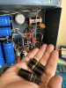
Those brown epoxy caps may have been original. Those are mylar caps, ElMenco branded in this case but I think they were made by Cornell-Dublier. Perfectly decent cap honestly, and they last just about forever. I ran a set through a dishwasher once just to see what would happen. Besides most of the print being gone, they still work perfectly fine.
 
If you have the gear to do so, confirm the frequency response if you use a resistor to eliminate the pot and set the sensitivity. If there is too much treble roll-off, experiment with small value caps across the resistor to restore the response.

Those brown epoxy caps may have been original. Those are mylar caps, ElMenco branded in this case but I think they were made by Cornell-Dublier. Perfectly decent cap honestly, and they last just about forever. I ran a set through a dishwasher once just to see what would happen. Besides most of the print being gone, they still work perfectly fine.

Thanks for the input Gadget!

That’s an interesting observation about the vintage of those caps. I don’t think they were original in this case, as they lacked the red paint pen QC marks on the solder joints that are elsewhere, but good to know they are pretty reliable in case I encounter them again in other gear.

Regarding the frequency response, I have not attempted measuring out an amp, ever. I have an oscilloscope and a function generator, but know nothing else about the proper measurement process. I’m sure it’s covered somewhere on here, I’ll poke around. Electrically, can you shed some light on what happens with the removal of the pot that necessitates another cap? My basic thinking was that it’s just a variable resistor, and could be swapped for the proper fixed value, but I’m assuming there is another property that needs consideration of which I am unaware, but eager to learn.
 
Possibly not original, but still probably quite old. I've got some in early 1960s gear.

Usual easy way of checking response without getting too nuts about it is to just do a square wave test, probably at 1khz. Can actually do this while the pot is still in, set the function generator so you get about 1 volt peak to peak on the output with the pot all the way up and note what it looks like. Drop the input sensitivity and wind up the generator to get the same sort of output. Fair bet you'll notice the leading edge of the square wave start to round over as the pot is turned down. Theoretical ideal is with the leading edge as square as it gets, without overshoot or a lot of rounding at the top. Overshoot would be a rising HF response, rounding would be a falling HF response. Square is flat response.


basically what you've got going on here is a simple RC low pass filter. The R is the pot, and the greater the amount of resistance between the input and the tube grid, the lower the frequency of the filter. The C is the effective capacitance of the tube * the tube gain. This is whats called the Miller capacitance. A 12AU7 doesn't have a ton of gain so it won't be extreme, and it may not be enough to care about but its just something to consider if you've got the ability to measure for it. Looks like it may already be compensated for with that RC network across the cathode resistor anyway. That will provide a bit of HF boost.
 
@elpulpo88
For those of us who will have to build from scratch, unless luck befalls us, what are the dimensions of the chassis? Just in case we want to copy as closely as possible. I'm not always one to do it. I like to work a layout for my own sensibilities but it's nice to know anyway.
Thanks,
John
 
@elpulpo88
For those of us who will have to build from scratch, unless luck befalls us, what are the dimensions of the chassis? Just in case we want to copy as closely as possible. I'm not always one to do it. I like to work a layout for my own sensibilities but it's nice to know anyway.
Thanks,
John

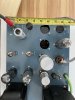
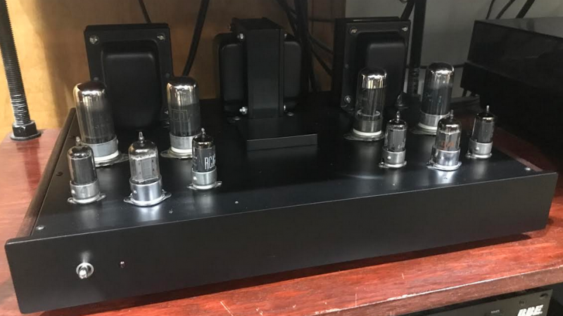
No problem. The chassis dimensions are 12.5”x9”x2.75”. Here is a picture that gives you an idea of the socket placement.

ED065040-C3D8-4449-8C17-56EA3F8F478C.jpeg
 
I would love to know more about your experience building this circuit from scratch. I have the best luck with pictures by clicking the camera icon in the toolbar for the reply.

I'll get my pics and info together and create a post (so as to not to hijack this one). The first I built has been stellar - great sounding and super reliable. I made some design choices that may not be ":super high end" cork sniffing but I tr
 
I would love to know more about your experience building this circuit from scratch. I have the best luck with pictures by clicking the camera icon in the toolbar for the reply.

I'll get my pics, schematic, parts list, etc and info together and create a post (so as to not to hijack this one). The first I built has been stellar - great sounding and super reliable. I made some design choices that may not be "super high end" cork sniffing but it's an easy circuit to go as crazy as you like (if you want).

Here's a few of the Serial Number 1 - the SN 2 in process is more elegant with cherry wood sides etc. This was my initial "will it work and sound good' - oh and yes... those are not 6v6s. I used 7C5 since I had a few dozen of NOS types. Of course easy to adapt by using the correct socket pin connections. I also built a "stereo" (not dual mono sorry) and used solid state (egad!) power supply rectification. SUPER quiet - zero hum, all voltages check to with a few percent of the schematic test points values.

 
The links don't show anything. The error message says I don't have permission to view the album.
 
Last edited:
My amps have been steady state for a while now, and my tinkering has been focused on an autoformer volume control based passive line stage for them, and a list of other projects I’ve been behind on.

That said, I was searching around for information on the RCA Hi-Fi line, and finally found a great article in an RCA publication from back then. The relevant pages are 60-65, and there’s also this great photo of ol’ Doc Olson.

40002C93-A02C-49C4-B854-D8391DD05101.jpeg

https://worldradiohistory.com/ARCHIVE-RCA/RCA-Broadcast-News/RCA-76.pdf
 
My amps have been steady state for a while now, and my tinkering has been focused on an autoformer volume control based passive line stage for them, and a list of other projects I’ve been behind on.

That said, I was searching around for information on the RCA Hi-Fi line, and finally found a great article in an RCA publication from back then. The relevant pages are 60-65, and there’s also this great photo of ol’ Doc Olson.

View attachment 2692665

https://worldradiohistory.com/ARCHIVE-RCA/RCA-Broadcast-News/RCA-76.pdf

I have that article - very interesting!
 
mmmmmmmhhhhh...LC-1A...most tasty. JVC did a woofer like that. And what a shock, Japan Victor Co....so they come by it honestly... :) 7C5 make for great 6V6 subs. I tend to remove the locking center clip from the socket as they are a right witch to get the tubes out again.

My SP10 interpretation goes something like this: 6H6Pi ltp input stage. 12BY7 drivers, and Sweep-of-choice for the finals. 31JS6C comes to mind with a properly reg'd, low impedance g2 supply at around 100V. OPT cloned fro the Cit.V at 4k a-a.
Douglas
 
Got my amps fully dialed in now. I finally got in and ditched the 3 remaining bumblebee coupling and input caps, and swapped in Jupiter copper and wax replacements. Took care of the small hum issues the amps had immediately, and definitely opened up the sound a bit more.

These amps sound so so so good. It’s a little wild they aren’t talked about more, I’m truly blown away in comparison to everything else I’ve ever heard or owned, and that list runs the gamut. Midrange and transparency like a SET, bass control and snap like something Ultralinear.

They are especially lovely with a 601C/614 speaker build I just finished, though I’m still waiting on better crossovers to show up. Jagusch, predictably. I took the amps, speakers, and passive line stage to a local diy audio meetup here in Brooklyn, and people seemed to agree with what I was hearing, even in a casual ad hoc setup.

I’m still considering axing the input sensitivity pot, as I really can’t come up with a use case where that would be particularly helpful, and I’d have to assume a fixed value resistor would be more transparent in the signal path. Other than that, I just need matching power cords, and a new power switch in one amp to replace its current one that likes to stay on sometimes even once flipped to the off position (a fun trick..). Then these puppies are fully done, as far as I’m concerned.

1E229C9D-E806-4A17-BF97-1C279557F7DF.jpeg 35092875-E60D-4D3C-BCF7-58C3B1903EFB.jpeg 3A7864FF-7A27-4E33-B998-57E6D069F735.jpeg 5FC92CF7-C1DB-419E-AB85-FA136C4C2C82.jpeg 3D5EA0BA-8613-41FB-9D6E-94810F770FF8.jpeg
 
Last edited:
No problem. The chassis dimensions are 12.5”x9”x2.75”. Here is a picture that gives you an idea of the socket placement.

View attachment 2640519

Beautiful amp! The only slight bit of friendly criticism I'd offer is the modern hardware - to keep my vintage gear looking more era-correct, especially when I need to replace rivets with screws, I discovered that McMaster Carr carries slotted binder-head screws that look exactly like those used in almost all electronics from the 1940s-60s. Most everything out there used 4-40s, with a few 6-32s and 8-32s bolting down transformers. McMaster Carr's shipping tends to be stupidly expensive, so I buy them in bulk. If you used slotted binder head screws, no one would ever know that the hardware isn't original, even that the can caps and such weren't originally attached with screws instead of rivets.

Once concession to modernity, I buy KEPS style locking nuts in bulk when I order screws. They make sure everything stays together nicely, and no one will know about them unless they're inside the chassis.

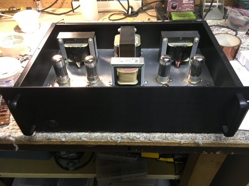
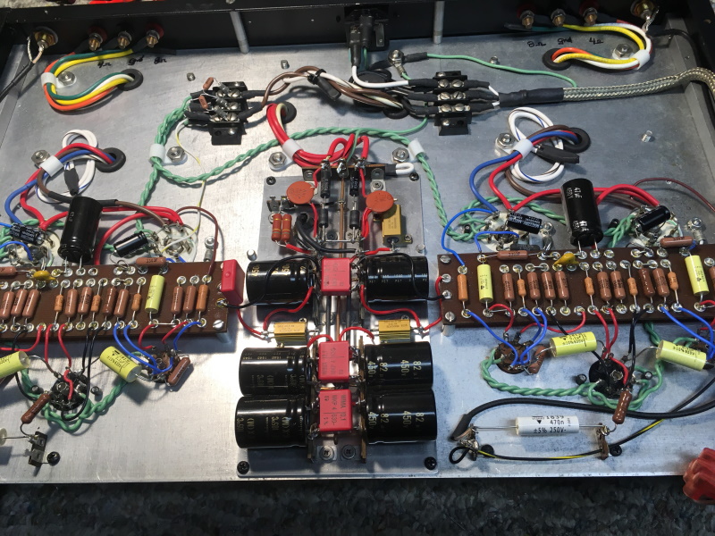
finished up the second diy version - sounds as good as the first.


Very nice! Which transformers did you use?
 
Back
Top Bottom