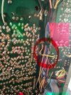
Hi all, just recapped my HK 330c on the tuner board. I followed the instructions provided from my supplier that I purchased the kit from and also looks at dlucy post/google drive photos of his rebuild of the 330c. I have lost the FM/AM signal after the recap. I have check polarity of the caps and made sure those are correct. the Wima caps are non-polar so I don't have to worry about "+" and "-" on the board, I hope. Doubled check my solder points. What am I missing here? I did notice that on the tuner board at C276, the marking say 100/10V. The capicator I remove was a 47uf @ 10V. I replaced it with a 47uf @ 10V, but I am still not able to get the FM/AM signal thru the receiver.


You are using an out of date browser. It may not display this or other websites correctly.
You should upgrade or use an alternative browser.
You should upgrade or use an alternative browser.
Recapping and restoring a Harman Kardon 330C
Are there pushbutton switches still available somewhere? Have a 330c with a dead speaker switch and the other apparently isnt much better. I've tried scraping the glue off an carefully edging up both sides with a razorblade, but it's not giving up and I don't want to break the hardboard

I've got two more HK330c to restore, so I'll be trying the TTA004/TTC004 and the MJE243/MJE253 combinations for the pre-drivers and drivers.
The SilPads are the only way to go for mounting the output transistors to the heatsink.
The tuning capacitor nylon wheel sure does come off easily... and the gears and cogs tend to come along... and they are a PITA to reinstall... so don't go pulling it off or allowing it to fall off.
You can find replacement meters for the units where they've died... but the backplate is the tricky bit to fabricate (since the replacement meters don't have that).
Replacing the transistors on the tuner board does make a difference in reception... except for the one FET. That one is impossible to replace.
The SilPads are the only way to go for mounting the output transistors to the heatsink.
The tuning capacitor nylon wheel sure does come off easily... and the gears and cogs tend to come along... and they are a PITA to reinstall... so don't go pulling it off or allowing it to fall off.
You can find replacement meters for the units where they've died... but the backplate is the tricky bit to fabricate (since the replacement meters don't have that).
Replacing the transistors on the tuner board does make a difference in reception... except for the one FET. That one is impossible to replace.
Switches from this C&K series are compatible and I have used them before on HK units of this vintage:Are there pushbutton switches still available somewhere? Have a 330c with a dead speaker switch and the other apparently isnt much better. I've tried scraping the glue off an carefully edging up both sides with a razorblade, but it's not giving up and I don't want to break the hardboard
DPDT push switch
4PDT push switch
6PDT push switch
Waiting to hear what comes out of the Toshiba experiment. Got double shipment.I've got two more HK330c to restore, so I'll be trying the TTA004/TTC004 and the MJE243/MJE253 combinations for the pre-drivers and drivers.
The SilPads are the only way to go for mounting the output transistors to the heatsink.
The tuning capacitor nylon wheel sure does come off easily... and the gears and cogs tend to come along... and they are a PITA to reinstall... so don't go pulling it off or allowing it to fall off.
You can find replacement meters for the units where they've died... but the backplate is the tricky bit to fabricate (since the replacement meters don't have that).
Replacing the transistors on the tuner board does make a difference in reception... except for the one FET. That one is impossible to replace.
Could you elaborate on the meter replacement process?
Good dealI'll share when I have proven, repeatable results. Until then it is just experiments.
Switches from this C&K series are compatible and I have used them before on HK units of this vintage:
DPDT push switch
4PDT push switch
6PDT push switch
It appears C&K switched F2UEE and F4UEE are the ones that will work. I'll order one each and give them a try.
Parts F2UEE TB and F4UEE TB are the sealed versions of the same, as @Namlook is using, but I can't find a source that has them in stock... so can't try them and confirm.
kgetchmaine
Active Member
Hey all, getting ready to recap my HK 330C and the softstart is where I want to begin since it is not working and getting lots of noise when powering on. I can see the 22uf 10V cap is showing lots of heat on it. Issue is, I do not have any 22uf caps on hand. I do have a 33uf 10V caps. Would using that be a no-no?
I generally use same uf but more volts if I dont have a particular cap on hand. Would doing so mess up the circuit? I am really unsure how that affects a circuit so would love to get some context in how-what-wheres of that. Will that defeat the design or compromise it? Thanks
I generally use same uf but more volts if I dont have a particular cap on hand. Would doing so mess up the circuit? I am really unsure how that affects a circuit so would love to get some context in how-what-wheres of that. Will that defeat the design or compromise it? Thanks
kgetchmaine
Active Member
Cool! So no harm to try the 33uf cap. Looks like I have a project after work! I do have some 22uf's coming from Mouser if the delay is too long for any reason. Thanks much!
kgetchmaine
Active Member
Question re: outhouse transistor 2SA844 on the power supply board. Assuming the same orientation for a TO-92 package the datasheet I found shows the pinout as ECB. When I tested mine from the peak indicates it is BCE. This is having the side with the transistor ID number facing me. Is this the proper orientation? If this is true, I need to orient the KSA1015 replacement 180 degrees. Unfortunately, I did not take a pic before I removed that transistor. Going by djucy's pic in earlier in this thread.
Thanks for this awesome writeup dlucy. Anybody have any suggestions for good caps to replace C3 and C4? The suggested replacement 647-UKW1H682MRD is in end-of-life and is no longer available. Thanks in advance.
If you are searching Digikey or Mouser, find on with the same ratings or higher that fit the space. Usually many optionsThanks for this awesome writeup dlucy. Anybody have any suggestions for good caps to replace C3 and C4? The suggested replacement 647-UKW1H682MRD is in end-of-life and is no longer available. Thanks in advance.
Ended up finding some good replacements.If you are searching Digikey or Mouser, find on with the same ratings or higher that fit the space. Usually many options
Does anyone have any suggestions for replacing D409 and D410 (varistor MV12Y) on the main amp board? I’m seeing suggestions in other threads to replace the same part with a series pair of diodes. Obviously going that route wouldn’t allow connection to the heatsink like the original parts do. Unsure of what my best plan of action here would be and appreciate any input. Thanks
Several of the "replace STV" threads include "how to" for the situation where the resulting double or triple diodes would be thermally connected and attachable to a heatsink or transistor. One of the "how to" threads is here https://audiokarma.org/forums/index.php?threads/my-stv-4h-workaround-credit-to-echowars.954104/
I gently pry open the connectors, bust out the epoxy, wire 2 1N4148s in series. There is a directional indicator on the board. Bend one lead on the striped end 90 degrees and close to the body. Make sure the bodies are in series and touching. Solder them, and cut the excess leads. Loosely bend the terminal wings kind of back together, loose enough to place the bodies inside. Technically, you should replace the epoxy, but I've found it works OK just shrink tubing the heads and gently clamping them in the wire holeEnded up finding some good replacements.
Does anyone have any suggestions for replacing D409 and D410 (varistor MV12Y) on the main amp board? I’m seeing suggestions in other threads to replace the same part with a series pair of diodes. Obviously going that route wouldn’t allow connection to the heatsink like the original parts do. Unsure of what my best plan of action here would be and appreciate any input. Thanks
Several of the "replace STV" threads include "how to" for the situation where the resulting double or triple diodes would be thermally connected and attachable to a heatsink or transistor. One of the "how to" threads is here https://audiokarma.org/forums/index.php?threads/my-stv-4h-workaround-credit-to-echowars.954104/
Thank you both.I gently pry open the connectors, bust out the epoxy, wire 2 1N4148s in series. There is a directional indicator on the board. Bend one lead on the striped end 90 degrees and close to the body. Make sure the bodies are in series and touching. Solder them, and cut the excess leads. Loosely bend the terminal wings kind of back together, loose enough to place the bodies inside. Technically, you should replace the epoxy, but I've found it works OK just shrink tubing the heads and gently clamping them in the wire hole
I stupidly didn't take photos of the underside of any of the boards on my unit and now have an issue. Can anyone explain what this ground(?) wire and cap is for and where it is supposed to go? The side that is connected is on the tuner board. Thanks again for bearing with my beginner struggles everyone.