• The move to the new server is done. There are some software and database maintenance updates in process. This has us passing the hat around to help out. We appreciate any donations. Seriously, even a dollar helps. The payment page may be found here - https://www.audiokarma.org/support.html

Recapping and restoring and upgrading a Heathkit AR-1515 receiver

dlucy

dlucy67 (Doug)
Staff member
Moderator
Subscriber
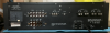
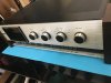
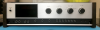
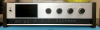
One of our outstanding local AK'ers, @nj pheonix , asked me to recap and restore his monster-of-a-receiver Heathkit AR-1515.
01 01 IMG_1689.png

It is quite a beast, lots of power, an unusual design (on the inside), has the rare Dolby FM card, and was a lot of fun (read as "learning experience") to work on. This will cover the unit, the recap (with BOM), the upgrades and the result.

FYI: He has the resulting kickass unit up over in a Bartertown thread.

There are a few threads here covering the amp-only version of this, the Heathkit AA-1515:

 
Last edited:
Register to hide this ad
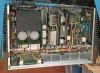
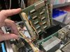
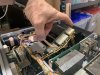
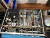
The modular card design isn't really a card cage, but instead it lets each card rotate on a single corner... it flips up so you can adjust or work on the card. Odd, but interesting....

04 01 IMG_2274.JPEG
04 02 IMG_2275.JPEG
04 03 IMG_2276.JPEG
04 04 IMG_2271.JPEG
04 05 IMG_2273.JPEG
04 IMG_2254 - Copy.JPEG
04 IMG_2297.JPG
04 IMG_2346 - Copy.JPG
 
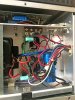
The chassis-attached part of the power supply was a bit more rugged and serious than I was expecting.

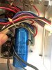
The two power reservoir caps used a bar to the main rectifier and to ground:

06 01 IMG_1826.JPG

06 02 IMG_1829.JPG

The main rectifier bridge was a serious, chassis-mount can type (but that didn't stop me from blowing it eventually):

06 03 IMG_1831.JPG

The lower voltage, 10V, was regulated... at 5A... so another serious can-style device:

06 04 IMG_1834.JPG
06 05 IMG_3362.JPG
06 06 IMG_1828.JPG

And one last rectifier made of just two diodes:

06 07 IMG_1827.JPG
 
The preamp and source selector board was the first modular card to be taken out.

07 01 IMG_2189.JPG

The selector shaft ran all the way forward and had to be disconnected before it would come out:

07 02 IMG_2179.JPG

The inputs came right off the rear input panel and into the selector:

07 03 IMG_2203.JPG

Oxidization?

07 04 IMG_3244.JPG

There were a few naughty tantalums in the signal path. They'll have to be replaced:

07 05 IMG_3238.JPG

This AR-1515 is the first "truly" vintage receiver I've seen that uses an opamp. Very cutting edge, Heathkit! Being an old opamp, it'll likely have a modern, higher performance replacement. We'll have to test to see if that makes a difference:

07 06 IMG_1803.JPEG

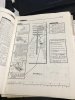
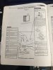
The Heathkit assembly manual did a great job of listing the parts and indicating how to test your work before final assembly:

07 07 IMG_1793.JPG
07 08 IMG_1799.JPEG
07 09 IMG_1800.JPEG

Sadly there were some parts which had Heathkit-only part numbers. Most of these were cross-reference-able at the Heathkit parts list sites like:

 
Thanks doug. Have had to repair old controllers at work using the metal can op amps.That IC was used in one of the units.
 
There were earlier Heathkits that used op amps. Both the AR-15 and AR-1500 had op amps in the FM IF section. The AR-1500 also had a single chip multiplex decoder, but that's not exactly an op amp. Looks like the mechanical engineers learned a few things about accessibility after the AR-15. The AR-15 mechanical layout was obviously done by a former automotive engineer that would start with a heater core, then build the entire car around it.
 
The Heathkit AR-1515 had an optional Dolby FM decoder board and the unit @nj pheonix asked me to restore included this rarity.

08 01 IMG_1735.JPG
 

Attachments

  • 08 02 IMG_1750.JPG
    08 02 IMG_1750.JPG
    52.9 KB · Views: 58
  • 08 03 IMG_1749.JPG
    08 03 IMG_1749.JPG
    40.4 KB · Views: 64
  • 08 04 IMG_1756.JPEG
    08 04 IMG_1756.JPEG
    52.7 KB · Views: 62
  • 08 05 IMG_1761.JPEG
    08 05 IMG_1761.JPEG
    44.6 KB · Views: 56
  • 08 06 IMG_1763.JPEG
    08 06 IMG_1763.JPEG
    40.4 KB · Views: 51
  • 08 07 IMG_1764.JPEG
    08 07 IMG_1764.JPEG
    44.6 KB · Views: 50
  • 08 08 IMG_1766.JPEG
    08 08 IMG_1766.JPEG
    44.1 KB · Views: 58
  • 08 09 IMG_1767.JPEG
    08 09 IMG_1767.JPEG
    42.7 KB · Views: 60
The control circuit board hosts all the front panel potentiometers and function switches.

09 01 IMG_2440.JPG

09 02 IMG_2443.JPG

09 03 IMG_2444.JPG

09 04 IMG_2445.JPG

09 05 IMG_2446.JPG

09 06 IMG_2447.JPG

09 07 IMG_2448.JPG

09 08 IMG_2449.JPG

09 09 IMG_2456.JPG

09 10 IMG_2467.JPEG
 
Each channel has its own power amp board, each board is on opposite ends of the chassis, has a plug for power, a RCA jack for input signal, and huge heatsinks for the output transistors.

10 01 IMG_1843.JPG

10 02 IMG_1835.JPG

10 03 IMG_1840.JPG

10 04 IMG_1848.JPEG
 
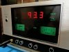
Another unusual bit on this receiver is the digital display. The AR-1515 is an analog tuner with a digital readout. The digital readout is really a frequency counter with digital display. So, the tuner tunes by analog, produces a signal, and the frequency counter counts it.

11 01 IMG_2400.JPEG

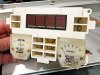
The digital readout sticks through the meter and indicator light assembly:

11 02 IMG_2476.JPG

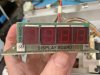
The digits are simple, vintage LED display modules:

11 03 IMG_0192.JPEG

11 05 IMG_0191.JPEG

11 06 IMG_0194.JPEG

Each plugged into a socket:

11 07 IMG_0202.JPEG

With a display driver board:

11 09 IMG_2391.JPG

11 10 IMG_2150.JPG

11 11 IMG_2173.JPG
 
The RF board was relatively simple... and had interesting adjustment screws sticking out the back...

12 01 IMG_2305.JPG

12 02 IMG_2317.JPG

12 03 IMG_2318.JPG

12 04 IMG_2278.JPG
 
The frequency counter, IF, and FM multiplex boards we very straightforward, easy to work on:

IMG_2153.JPG

IMG_2207.JPG

IMG_2238.JPG
 
Ok, down to the recap/restore/upgrade.

The preamp / selector card got:

all carbon comp resistors replaced with high precision metal film resistors
all electrolytic caps were replaced with low leakage Nichicon KL series electrolyitc caps
the small signal transistors were replaced with modern low noise devices
the one diode, a Zener, got replaced with a modern version
and the coupling caps were replaced/upgraded to Panasonic film caps

and finally...

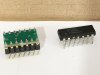
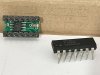
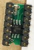
the one opamp got replaced with a modern device... which required using a German-built SMD to DIP adapter.

15 01 IMG_3263.JPG

Replaces the original opamp with LME49720 mounted on a SMD-to-DIP adapter from eBay seller revox-online

15 02 IMG_2392.JPEG

15 03 IMG_2393.JPEG

15 04 IMG_2394.JPEG

15 05 IMG_2395.JPEG
 
Last edited:
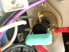
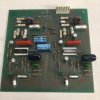
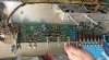
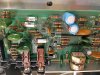
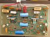
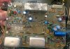
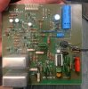
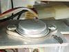
The power supply board was nearly 100% rebuilt.

16 01 IMG_2568.JPG

It didn't make any sense to put in axial electrolytics at premium cost when Nichicon PW series, mounted on their sides, would work best and be inexpensive:

16 02 IMG_2588.JPG

Their leads just had to be extended with some station wire and heat shrink tubing:

16 03 IMG_2585.JPG

16 03 IMG_2589.JPG

The original design omitted unnecessary holes for unused leads:

16 04 IMG_2596.JPG

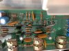
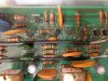
And the one strange cap + resistor combo was repeated, just with modern, better components:

16 05 IMG_2597.JPG 16 06 IMG_2598.JPG

and the modern ones:

16 08 IMG_3126.JPG
 
Last edited:
Back
Top Bottom