• The move to the new server is done. There are some software and database maintenance updates in process. This has us passing the hat around to help out. We appreciate any donations. Seriously, even a dollar helps. The payment page may be found here - https://www.audiokarma.org/support.html

Recapping and restoring and upgrading a Heathkit AR-1515 receiver

I too am curious to see (hear) from changes in sound before and after the job. When I try to access the Bartetown thread, I get an error: You do not have permission to view this page, although I am logged, like now. Curious ...

Bartertown is one of those extras you get when you become an AK subscriber. I couldn’t live without it.
 
I did some estimates.

Recap only (with Dolby board) : 67,71 CND -->51,50 USD.

Recap plus metal film resistors (power supply, preamp, power amp boards), some diodes and transistors (not the output MJ802) and the opamp LME49720 :
254,14 CND --> 193 USD.

Finally the adapter for the opamp :
25 CND --> 20 USD.

In my case, if I go ahead with the job, I will not use the metal film resistors, as my AR 1515 is already built with carbon film.
Unless the knowledgeable here convince me, that the change would significantly affect the result.
 
I am curious as to why you bothered to do the Dolby board since it wasn't adopted by most FM stations that I know of?


Larry
 
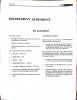
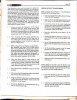
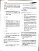
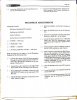
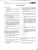
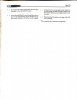
For those of you who need to align your FM or AM tuners in the Heathkit AR-1515 receiver, here are the instructions:
 

Attachments

  • JotNot_01-04-2020-page-1.jpg
    JotNot_01-04-2020-page-1.jpg
    47.5 KB · Views: 49
  • JotNot_01-04-2020-page-2.jpg
    JotNot_01-04-2020-page-2.jpg
    87.1 KB · Views: 48
  • JotNot_01-04-2020-page-3.jpg
    JotNot_01-04-2020-page-3.jpg
    77.1 KB · Views: 41
  • JotNot_01-04-2020-page-4.jpg
    JotNot_01-04-2020-page-4.jpg
    58.8 KB · Views: 40
  • JotNot_01-04-2020-page-5.jpg
    JotNot_01-04-2020-page-5.jpg
    62 KB · Views: 41
  • JotNot_01-04-2020-page-6.jpg
    JotNot_01-04-2020-page-6.jpg
    20.5 KB · Views: 42
Doug, just curious as to why you used 12K instead of the original 10k power supply capacitors?
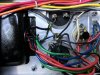
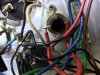
I have 3 AR-1515s and 3 AA-1515s which I plan on recapping in the near future. I took the bottom panel, power amp boards and heat sinks off of the one AA-1515 that I use for the deck speakers to check the capacitors on those two boards and found a couple of the nonpolarized ones are starting to leak. The bottom panel was taken off to check the wiring of the power supply 10K electrolytics. I found lead wire ( lead wire like those on a radial capacitor) was used instead of 14 gauge solid wire from the lugs of the rectifier to the lugs on the capacitors on both the B+ and B- sides. Several ground wires were soldered to a lead wire which was soldered to a chassis grounding lug.
Mind you, this amp was not assembled by me, although I failed to notice the problem several years ago when I had the bottom off to replace the feet and also install LED indicator lamps.
24FE6242-608A-4D55-9A27-27BDE8A9598F.jpeg01B0E942-B058-4477-9F36-32BD98D39005.jpeg
 
Last edited:
Doug, just curious as to why you used 12K instead of the original 10k power supply capacitors?

just increasing the depth of power reserves and reducing ripple... a little. Not required, just an opportunity for easy upgrade.

I have 3 AR-1515s and 3 AA-1515s which I plan on recapping in the near future. I took the bottom panel, power amp boards and heat sinks off of the one AA-1515 that I use for the deck speakers to check the capacitors on those two boards and found a couple of the nonpolarized ones are starting to leak. The bottom panel was taken off to check the wiring of the power supply 10K electrolytics. I found lead wire ( lead wire like those on a radial capacitor) was used instead of 14 gauge solid wire from the lugs of the rectifier to the lugs on the capacitors on both the B+ and B- sides. Several ground wires were soldered to a lead wire which was soldered to a chassis grounding lug.

I will admit that when I realized I wanted to replace that ground bus bar and the associated bars to the caps, I wondered “where the heck am I gonna find solid wire THAT thick”... but then I remembered Amazon.com... and my OCD kicked in. “maybe even THICKER is a good idea....”

homebuilt Heathkit have never crossed my workbench... to my knowledge... but I think that just means I wasn’t looking as critically as I could. It is smart, I think, to check for that right off the bat. I’ve made plenty of mistakes on units that were factory wired, so there must be plenty of homebuilt units that aren’t perfect.

what are your plans for your units? Partial recap? Full recap? Something else?
 
I’m thinking of doing a partial recap on the AR-1515s since I don’t use the the tuners and IF boards any more and pretty much a complete recap on the AA1515s. Serveral years ago I installed a pair of Anthony Holton’s amps in one the AR-1515s. In that one I will do everything but the output amps, the tuner and IF boards. I’ll use the 12K capacitors in that AR-1515. It gets used in the master bedroom. I also have an AR-1650 that has Holton amps installed that gets used in my garage which I should recap eventually.
Larry
 
Increasing the value of the main filters is not a problem. Typically, one needs to look for something that will fit properly in the same space. My Fisher 600-T projects replace a pair of 4000 µF 40 V capacitors with 10,000 µF 100 V. The 100 V is overkill but 63 V were not available in a usable physical size.

As for wiring, the main bus between the + terminal of one capacitor and the - terminal of the other should be heavy wire. Even doubling up is good. That wire needs to take the shortest possible path and the capacitors should be rotated to allow that. Then there should be only ONE wire in (transformer center tap) and ONE wire out to a point where it can then be split off. These connections should be at the mid point of the bus and as close together as possible. This is so that the extremely high ripple currents in the bus between the capacitors is resolved before going out on the load wire. Chassis ground should be at only ONE point. All other grounds should follow as branches of a tree with no loops, though that could be difficult at the input jacks.
 
Speaking of home built, one of AR-1515s that I bought off of eBay several years ago did not have any of the leads cut shorter than a quarter of an inch on any of the boards. Gave me the creeps like somebody with really really really long fingernails! I’ll have take pictures of some of the boards and post
them.
I built my original AR-1515 in 1977 along with an AD-1307 Audio Control Center. They were the last ones that I built. I also built an AJ-29, an AA-29, a tachometer and an AD-1305 Audio Equalizer.
I really enjoyed building them but then couldn’t wait to get them done. More likely to make mistakes.
None of the Heathkits that I have now were factory built that I know of.
Larry
 
Man, quite an overhaul.

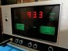
I don’t suppose the manual has much info on the frequency counter, does it? I have a nice working AR-1515 but the counter is wonky.
 
This is a great thread! My Heathkits include 3 AA-29 amplifiers (the first of which I built in March of 1976), 2 AR-29 receivers (1 is now my son's), 1 AJ-29 tuner, 1 AA-2010 quadraphonic amplifier (basically 2 AA-29s in one chassis except it uses MJ2841 instead of 2N3055 outputs and 39 volt rails instead of 35 volt), 1 IG-28 color bar/dot generator, and a handheld capacitor tester of which I can't remember the model number and it's not here right now.

The -29 pieces were bought to build my classic quad system and I have always preferred separates instead of basing a quad system around a quad receiver. I don't think any of them were factory-built. I found unsoldered connections in some of them. Through the years, I have also replaced various capacitors, like the rail filters in all of them except the AA-2010.

Like Larry, I really enjoyed building the ones I did but couldn't wait to get them done. I built the AA-29 in two days instead of the four it was supposed to take. I dated the pages in the manual - 3/16 through 3/18/1976. I also kept at the color bar/dot generator until it was done.

I just got done going through all the audio pieces to be sure they are still in spec and some sliders were getting a bit (and just a bit) noisy so they got Deoxit and Faderlube. Voltages were all OK except one of the monitor input preamps in the AA-2010 had a bad transistor so it was replaced.

I thoroughly enjoy it. As far as I'm concerned, Heathkit was/is one of the best companies the USA ever produced.

Doug
 
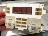
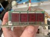
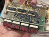
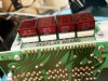
I would suggest using heat sinks on the three LED readout driver Integrated circuits, they do get quite warm.
Larry
 
Here are the lines I gathered for potential replacements:


Readout IC451,IC452,IC453 3 IC IC 9368 DIP16 IC
Readout Q451 1 Transistor BJT SM62186 417-284 SM62186 PNP 15V 200mA 850MHz BJT 2N5401 583-2N5401-F
Readout R451 1 Resistor Carbon Composition 470 r 1/2 W 10% Metal Film 470 r 1/2 w 1% YES 71-CMF55470R00FKR6
Readout R452,R453,R454 3 Resistor Carbon Composition 220 r 1/2 W 10% Metal Film 221 r 1/2 W 0.5% YES 71-CMF55-D-221/R
Readout V451,V452,V453,V454 4 LED module Red 7-segment common cathode, 19 mm x 12.6 mm x 8 mm, Forward Current 20 mA, Forward Voltage: 2 V LED Module 604-SC56-21SRWA or 743-INND-TS56RCB

All those were taken from the first page of the READOUT BOARD PDF that I sent you. F9368PC from the actual chips and 9368 from the parts list are the only ref numbers I have.
 

Attachments

  • 63605FB8-814E-433F-972A-282B4801CDE0.jpeg
    63605FB8-814E-433F-972A-282B4801CDE0.jpeg
    61.8 KB · Views: 35
  • 836382F7-E006-4431-B806-51775AE41517.jpeg
    836382F7-E006-4431-B806-51775AE41517.jpeg
    86.5 KB · Views: 36
  • A2E7A8D7-A1AB-4CBA-A893-7426FB2FE915.jpeg
    A2E7A8D7-A1AB-4CBA-A893-7426FB2FE915.jpeg
    71.3 KB · Views: 33
  • 78716479-A79C-410B-B6AA-502CD0B2B9DE.jpeg
    78716479-A79C-410B-B6AA-502CD0B2B9DE.jpeg
    82.5 KB · Views: 35
  • EA6D48B1-3A3A-42E2-B68E-E6DCED929081.jpeg
    EA6D48B1-3A3A-42E2-B68E-E6DCED929081.jpeg
    97.5 KB · Views: 32
  • 4B5CA0B9-AAAB-4092-A996-E519BD730577.jpeg
    4B5CA0B9-AAAB-4092-A996-E519BD730577.jpeg
    45.1 KB · Views: 33
  • CDBAFD93-1D11-4445-888E-DD1D7CDD4C41.jpeg
    CDBAFD93-1D11-4445-888E-DD1D7CDD4C41.jpeg
    93.8 KB · Views: 32
  • A9BF8EDF-BA3A-4CB1-8B9A-84731317FFA8.jpeg
    A9BF8EDF-BA3A-4CB1-8B9A-84731317FFA8.jpeg
    104.4 KB · Views: 33
  • CE655C14-44AD-40AB-8A1D-1567D2302F83.jpeg
    CE655C14-44AD-40AB-8A1D-1567D2302F83.jpeg
    99.3 KB · Views: 39
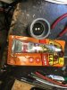
4B8EE3AA-90FD-409F-B2E2-325A764D49D2.jpeg 245CE9B7-EBDE-435A-AC7F-033FED2A8007.jpeg 4B8EE3AA-90FD-409F-B2E2-325A764D49D2.jpeg Well, Doug, I ended up getting only capacitors for the output amps and the power supplies. I’ve recapped the output amps, their power supply capacitors and the power supply board of the AA-1515 I posted pictures of in an earlier post. My soldering iron doesn’t heat up enough to solder the new solid wires in the ground buss, so I’m in limbo until the new arrives later in the week. I had a 1.25 inch PVC threaded pipe end cap that was laying around in my garage that was about the right size to glue in a Nichicon 10K uF 80V capacitor. I drilled a 7/8” hole in the end for the terminals. I used some Gorilla Glue clear grip to cement it in place. I bought some 1.25” female adapter for PVC conduit, cut off the non-threaded end and glued the capacitor in the threaded end. No need to drill a hole in adapter. Pictures of the capacitors installed, the new ground buss wires and the adapter uncut with capacitor and cement.

Larry
 
Back
Top Bottom