

You are using an out of date browser. It may not display this or other websites correctly.
You should upgrade or use an alternative browser.
You should upgrade or use an alternative browser.
Recapping and restoring and upgrading a Heathkit AR-1515 receiver
- Thread starter dlucy
- Start date

lrb1951
JBL L110 Nut
The larger gauge wire is real fun to thread through the holes on those ground lugs!
I bought a pair of 15K uF 100V capacitors for power supply in the AR-1650. They have the threaded lugs, hope that I’ll be able to just unscrew the screws and clamps and the new ones will fit. The AR-1650 came with 12K capacitors.
Larry
I bought a pair of 15K uF 100V capacitors for power supply in the AR-1650. They have the threaded lugs, hope that I’ll be able to just unscrew the screws and clamps and the new ones will fit. The AR-1650 came with 12K capacitors.
Larry
lrb1951
JBL L110 Nut
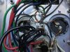
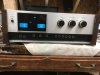
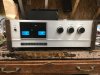
I finished all the soldering, installed the output amp boards and their heat sinks, and fired it up. In short order I started to smell something and then saw smoke from the left output amp board. Discovered that I managed to bend one of the leads of one the output transistors between the heat sink and the transistor’s socket. Should have done a better job of checking to make sure that the output transistors weren’t shorted to ground. Used a good board from one of several spare AR-1515s that I have and swapped out the capacitors. Didn’t feel up to trouble shooting the original board. Doubled checked for shorts and fired it up again. This time there was music coming from the speakers. Here’s a couple of shots of the completed grounding lugs and output amp’s power supply. Larry

lrb1951
JBL L110 Nut
Well, I finished recapping the power supply in the AR-1515 with updated output amps yesterday. I drilled out the the lug rivets on the original 10K uF capacitors making it fairly easy to solder them to the new capacitors’ snap in type lugs. Leaves me with 2 AA-1515s, 2 AR-1515s, the AR-1650 and the large power supply capacitors in the AA-29 to do.
Larry
Larry

For those of you who need to align your FM or AM tuners in the Heathkit AR-1515 receiver, here are the instructions:
I am just starting work on an AR-1515 and wanted to say thanks for all of the detailed information.
I am quite surprised at the quality level of the receiver.
So far I have just cleaned the controls, replaced a couple of bulbs and cleaned the tuning cap. I also had to fix the power switch, it was a bit sticky and needed an extra screw. Once I have everything working and within spec I will start to replace the caps and other parts.
I am at the point where I am aligning the tuner. Could you possibly post a picture of the manual showing the adjustment points as referenced by the alignment procedure, I think it's on Page 31? For example the board silkscreen does not indicate the the caps or coils in the section with the tuning capacitor. T121,L104,T105,C122,C131 and C136. Also the step for the Mixer Transformer calls for T123 to be adjusted. I can't find this.
Did you leave the speaker terminals as they came or replace them?

Doug G.
Lunatic Member
I have always left the terminals original, too, even the ones that are screws with lugs to tighten down on a bare/tinned wire, as much a pain in the arse as they are.
Larry, on my -29 units, when the replacement main filters have screw terminals, I use ring lugs from an automotive kit, install them under the screws, and solder all the wires to them.
If you need information on what caps will fit into the original clamps. I believe Newark still sells the large size power caps and I can get the numbers and post them. I have also posted them, in the past, in threads about the AA-29 or AR-29.
Doug
Larry, on my -29 units, when the replacement main filters have screw terminals, I use ring lugs from an automotive kit, install them under the screws, and solder all the wires to them.
If you need information on what caps will fit into the original clamps. I believe Newark still sells the large size power caps and I can get the numbers and post them. I have also posted them, in the past, in threads about the AA-29 or AR-29.
Doug
lrb1951
JBL L110 Nut
Thanks, Doug but I have already bought 8200 uF caps for the output amps’ power supply. I’ll do the same thing I did with the capacitors in the other two I have done.
Since I have 3 AR-1515 receivers for spare parts, I installed the proprietary speaker out jacks from one of them on the back side of the AA-29. Then the speakers are much easier to connect to it at any location that I have an AR-1515 or AA-1515. I also plan on installing one of the speaker muting circuits from one of them in the AA-29. I just have to figure out how much current it draws to design a voltage reduction circuit since the AA-29 has a 50 volt supply and the muting circuit needs only 10 volts.
I have a Heathkit AP1615 Preamp that I am going to order new caps for here in the near future. I bought an assembly manual for it via eBay last week. I opened it up yesterday to take a look. It had a volume level difference between the channels the last time I had used it. I suspect that it could be a bad capacitor or a cold solder joint. I did find one unsoldered ceramic capacitor lead on the circuit board on power supply side. Whoever built it missed it.
Larry
Since I have 3 AR-1515 receivers for spare parts, I installed the proprietary speaker out jacks from one of them on the back side of the AA-29. Then the speakers are much easier to connect to it at any location that I have an AR-1515 or AA-1515. I also plan on installing one of the speaker muting circuits from one of them in the AA-29. I just have to figure out how much current it draws to design a voltage reduction circuit since the AA-29 has a 50 volt supply and the muting circuit needs only 10 volts.
I have a Heathkit AP1615 Preamp that I am going to order new caps for here in the near future. I bought an assembly manual for it via eBay last week. I opened it up yesterday to take a look. It had a volume level difference between the channels the last time I had used it. I suspect that it could be a bad capacitor or a cold solder joint. I did find one unsoldered ceramic capacitor lead on the circuit board on power supply side. Whoever built it missed it.
Larry
Last edited:
Does anyone have page 31 of the assembly manual?
Any idea where I might find a set of speaker connectors?
I have been playing around and found a couple of interesting issues. I have not replaced parts yet.
The center tune meter is off at turn on and only centers after a 5 min warm up. Not sure where in the circuit this is coming from but it should be straight forward to figure out with some freeze spray, I hope. Also the 100K pot for the center tune is a bit touchy, I might replace it with a 10 turn. Maybe it's just the pot?
With the tone defeat off the left channel's frequency response is off in the low end. If I crank up the bass it evens out. I don't necessarily think it's the pot because the response is still linear when I change it. Maybe a cap is bad? If I switch the tone defeat on it's even on both channels.
Bob
Any idea where I might find a set of speaker connectors?
I have been playing around and found a couple of interesting issues. I have not replaced parts yet.
The center tune meter is off at turn on and only centers after a 5 min warm up. Not sure where in the circuit this is coming from but it should be straight forward to figure out with some freeze spray, I hope. Also the 100K pot for the center tune is a bit touchy, I might replace it with a 10 turn. Maybe it's just the pot?
With the tone defeat off the left channel's frequency response is off in the low end. If I crank up the bass it evens out. I don't necessarily think it's the pot because the response is still linear when I change it. Maybe a cap is bad? If I switch the tone defeat on it's even on both channels.
Bob

Does anyone have page 31 of the assembly manual?
I have a copy, but I can't get back to it until after the pandemic isolation stuff ends.
I am at the point where I am aligning the tuner. Could you possibly post a picture of the manual showing the adjustment points as referenced by the alignment procedure, I think it's on Page 31?
I can, but not until after the pandemic isolation stuff ends.

I have a copy, but I can't get back to it until after the pandemic isolation stuff ends.
Thanks Doug.
I think the alignment is still decent but I would like to run through it anyway. The tuner is actually quite impressive.
Someday this lockdown will end...........
Bob
I have got the AR-1515 working, after cleaning, recapping and aligning the tuner. I am having one problem still with the tuner, the center tuning is drifting.
I have tried to replace components and check the circuit but I still get the same result.
If I turn the receiver on it needs to warm up for about 10 min until the center tuning becomes stable.
For example.. If I turn it on and let it warm up then make the center tuning perfect and shut it down and let it cool it's quite a ways off when I restart again.
When it's cold and I start the tuning is not right as stations do not have symmetry from left to right on the meter.
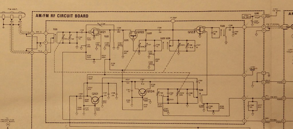
I removed the wire for the AFC circuit that comes from the IF board and goes to the RF board. On the IF board side I should see voltage that represents an error that get's sent to the varactor diode in the front end to correct the drift.
If I use a DC power supply connected to the AFC input on the front end and swing the power supply about a volt and a half I get a response that is shown on the center tuning meter. Seems correct.
When I measure the signal that drives the AFC circuit on the front end from the IF board I get hardly any change. The weird part is that the same signal that drives the center tune meter is the same signal that drives the AFC.
I wonder if this is just a problem with all AR-1515's?
Larry has sent me a scan of the manual that describes some of the FM section however it's silent on the AFC circuit.
Any ideas?

I have tried to replace components and check the circuit but I still get the same result.
If I turn the receiver on it needs to warm up for about 10 min until the center tuning becomes stable.
For example.. If I turn it on and let it warm up then make the center tuning perfect and shut it down and let it cool it's quite a ways off when I restart again.
When it's cold and I start the tuning is not right as stations do not have symmetry from left to right on the meter.
I removed the wire for the AFC circuit that comes from the IF board and goes to the RF board. On the IF board side I should see voltage that represents an error that get's sent to the varactor diode in the front end to correct the drift.
If I use a DC power supply connected to the AFC input on the front end and swing the power supply about a volt and a half I get a response that is shown on the center tuning meter. Seems correct.
When I measure the signal that drives the AFC circuit on the front end from the IF board I get hardly any change. The weird part is that the same signal that drives the center tune meter is the same signal that drives the AFC.
I wonder if this is just a problem with all AR-1515's?
Larry has sent me a scan of the manual that describes some of the FM section however it's silent on the AFC circuit.
Any ideas?
I can not find anything wrong with this circuit other than it drifts.
Using a Sencore SG80 I bypassed the front end and sent a 10.7 IF signal directly to the AM/FM IF board. I turned the generator on and let it warm up.
When I power up the receiver cold with the 10.7 signal into the IF board the center tune meter is off to the left quite a bit. Once I let it warm up for 15 min or so the meter is centered a bit to the right.
I used some freeze spray and found that IC203, IC203 and IC204 have lots of temperature sensitivity. Especially IC203, IC202. In the manual it shows this to be a MC1327P however I have a ULN2111A installed. It appears from looking at data sheets that they are equivalent parts but maybe one is better than the other, not sure. Also I have an MC9601 installed for IC 204, the manual calls out a MC8601.
I had ordered a ULN211A and 9601DMQB (mil spec version) over the weekend.
I ordered a manual for the AR-1215 and it arrived today. Low and behold written in red ink on the front page:
"Some Drift Is Normal"
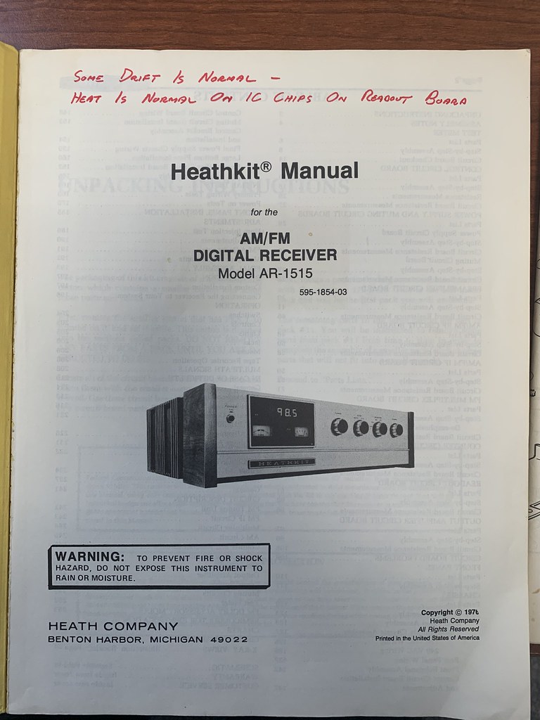
So is this just simply a flawed circuit design? Am I chasing my tail? Do they all drift? Do some receivers have better parts installed than others?
The ULN2111A dates to the late 1960's, it's a really old design. The manual calls for the MC1327P however I think the manual is in error. The MC1327P is for a video circuit. The MC1357 has a cross reference to the ULN2111A and shows it as a replacement for the ULN2111A.
I am going to install the new parts and see what happens.
Using a Sencore SG80 I bypassed the front end and sent a 10.7 IF signal directly to the AM/FM IF board. I turned the generator on and let it warm up.
When I power up the receiver cold with the 10.7 signal into the IF board the center tune meter is off to the left quite a bit. Once I let it warm up for 15 min or so the meter is centered a bit to the right.
I used some freeze spray and found that IC203, IC203 and IC204 have lots of temperature sensitivity. Especially IC203, IC202. In the manual it shows this to be a MC1327P however I have a ULN2111A installed. It appears from looking at data sheets that they are equivalent parts but maybe one is better than the other, not sure. Also I have an MC9601 installed for IC 204, the manual calls out a MC8601.
I had ordered a ULN211A and 9601DMQB (mil spec version) over the weekend.
I ordered a manual for the AR-1215 and it arrived today. Low and behold written in red ink on the front page:
"Some Drift Is Normal"
So is this just simply a flawed circuit design? Am I chasing my tail? Do they all drift? Do some receivers have better parts installed than others?
The ULN2111A dates to the late 1960's, it's a really old design. The manual calls for the MC1327P however I think the manual is in error. The MC1327P is for a video circuit. The MC1357 has a cross reference to the ULN2111A and shows it as a replacement for the ULN2111A.
I am going to install the new parts and see what happens.
Doug G.
Lunatic Member
I don't think Heath would have left that design with that much drift, especially when previous deigns work the way they are supposed to. With my -29 series receivers/tuners, the center tune meters are pretty much right there at power up, maybe a needle width, or so, off.
It may have to do with the substitutes. In one of my AJ-29 tuners, the Motorola MC1305 FM demodulator gave out with the right channel being much lower in volume than the left channel. The MC1305s are virtually unobtainium and I was able to get an LM1305 (Texas Instruments) as a substitute. The schematics and specifications of the two chips are virtually identical. However, the LM1305 doesn't seem to be quite up to the MC1305. The basic characteristics (separation, sensitivity. etc.) are fine but it take a few minutes for the mute to release and the voltage to make it do so seems to be there. Some of the other alignment adjustments don't work exactly as the original chip did either.
Doug
It may have to do with the substitutes. In one of my AJ-29 tuners, the Motorola MC1305 FM demodulator gave out with the right channel being much lower in volume than the left channel. The MC1305s are virtually unobtainium and I was able to get an LM1305 (Texas Instruments) as a substitute. The schematics and specifications of the two chips are virtually identical. However, the LM1305 doesn't seem to be quite up to the MC1305. The basic characteristics (separation, sensitivity. etc.) are fine but it take a few minutes for the mute to release and the voltage to make it do so seems to be there. Some of the other alignment adjustments don't work exactly as the original chip did either.
Doug
Maybe at the time this unit was built they only had the older parts. I do suspect that this is a problem on all units to some degree.
The front end responds perfectly to a change in AFC voltage being fed to it. The problem is that the circuit that develops the error voltage to correct for drift in the front end is thermally unstable. So the part of the circuit that is designed to correct the problem actually adds to it.
I am not sure if it’s the IF amplification between filters or the detector.
I am going to play around a bit more by injecting signals directly into subsections of the board to see if I can tell where the instability is coming from.
I was also thinking about putting heat sinks on the IC’s to see if that helps. It may just take longer to settle the center tuning out.
The front end responds perfectly to a change in AFC voltage being fed to it. The problem is that the circuit that develops the error voltage to correct for drift in the front end is thermally unstable. So the part of the circuit that is designed to correct the problem actually adds to it.
I am not sure if it’s the IF amplification between filters or the detector.
I am going to play around a bit more by injecting signals directly into subsections of the board to see if I can tell where the instability is coming from.
I was also thinking about putting heat sinks on the IC’s to see if that helps. It may just take longer to settle the center tuning out.
So it looks like the problem may be solved!
I only received two of the three IC's, ULN211A (IC203) and 9601DMQB (IC204). I installed sockets for them and had to realign the center tuning meter.
I tested the receiver last night for a couple hours with the IF 10.7 feed from the signal generator into the board and the center tuning did not move.
This morning I reassembled everything and it's working with no drift.
Thanks to everyone for the help! Sorry to hijack the thread.
One last thing I did... I ordered new filter caps that were the same physical size as the originals. They were a bit higher in uF, 13K vs. 10K and 100V vs. 55V.
I removed the terminals from the old caps by drilling them off by hand with a drill bit. The material is soft and it only takes a couple min to do it.


I only received two of the three IC's, ULN211A (IC203) and 9601DMQB (IC204). I installed sockets for them and had to realign the center tuning meter.
I tested the receiver last night for a couple hours with the IF 10.7 feed from the signal generator into the board and the center tuning did not move.
This morning I reassembled everything and it's working with no drift.
Thanks to everyone for the help! Sorry to hijack the thread.
One last thing I did... I ordered new filter caps that were the same physical size as the originals. They were a bit higher in uF, 13K vs. 10K and 100V vs. 55V.
I removed the terminals from the old caps by drilling them off by hand with a drill bit. The material is soft and it only takes a couple min to do it.