• The move to the new server is done. There are some software and database maintenance updates in process. This has us passing the hat around to help out. We appreciate any donations. Seriously, even a dollar helps. The payment page may be found here - https://www.audiokarma.org/support.html

Rek-O-Kut Rondine Jr. L-37 Restoration Begins.

So the main bearing parts have cleaned up pretty nicely so far. The thing will spin a very long time.

attachment.php
attachment.php


Looks like years of resting on a ball bearing have caused a little divot.

attachment.php


You can see one of the old dry and cracked grommet in this shot.

attachment.php
attachment.php


I think I could still work on shining these up more.

.
 
Last edited:
attachment.php


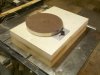
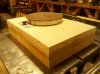
I just glued this up. I had exactly the right amount of extra material around the make a "working" plinth--something decent to have it in while I work through the learning curve.

It's made from (top to bottom)

2 layers of 3/4" Home Depot birch plywood (I see what they say about the voids)
4 Layers of 3/4" MDF
1 layer 1/2" MDF to cap the bottom

I didn't figure an arm board into this. I hope that doesn't come 'round to bite me in the ass.

attachment.php
 

Attachments

  • Plinth Build 21.jpg
    Plinth Build 21.jpg
    105.3 KB · Views: 329
  • Plinth Build 22.jpg
    Plinth Build 22.jpg
    95.2 KB · Views: 329
Looking good, when it comes time for mounting a tonearm you can just drill a hole from the bottom slightly larger then the hole need for the tonearm. Just make sure you don't go all the way through to the top.

Looking forward to seeing more pics, Chuckles :)
 
Nice work.What type of glue did you use and what kind of clamps did you use for the glue up? I will be interested to know if the massive plinth greatly reduces the noise floor.
Dave
 
Nice work.What type of glue did you use and what kind of clamps did you use for the glue up? I will be interested to know if the massive plinth greatly reduces the noise floor.
Dave

I just used basic wood glue (lots of it) and clamped it between scrap boards using bar clamps.

Last night, I glued it up it in two sections; the top three layers and the bottom three. Today I cut the motor hole in the separate sections then glued them together and capped the bottom with a 1/2 MDF.

I'll likely trim it out with painted poplar or MDF because I don't much care for the look of the exposed layers.

attachment.php
 

Attachments

  • Clamped.jpg
    Clamped.jpg
    99.7 KB · Views: 201
Last edited:
Yep, all you need is a big enough hammer.
I figure, if i need to, I can build it up another layer or two with an armboard cut out. Or I could drill up from the bottom with the drill press at work. Or even cut that left third of the plinth right off, modify it, and reconnect it using the separation as an isolation benefit (like I've seen in some plinth designs)

Or I could not mount the arm at all, but just sit next to it holding the arm real steady while it tracks across the record.

:scratch2:
 
Will you use a jig provided by the arm maker to determine the distance of the arm pivot to the spindle?Why would you need to drill up from the bottom?
Dave
 
Will you use a jig provided by the arm maker to determine the distance of the arm pivot to the spindle?Why would you need to drill up from the bottom?
Dave
I don't know if jigs are available for the arms I'm considering, however, I will know the prescribed distance from the spindle to mount the arm as well as the diameter of the bore. Drilling up from the bottom would just be one way to run the cable out.

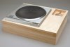
But I've decided to bore out a void at the arm mounting location and re-cap the plinth with another sheet of 1/2 birch ply with an armboard to cover the void like kind of like this (only a lot more crude):

attachment.php


attachment.php


This picture is from this excellent site:
http://www.soundfountain.com/amb/sp10plinth.html
 

Attachments

  • sp10porterbase400b.jpg
    sp10porterbase400b.jpg
    74.5 KB · Views: 330
  • sp10porterbase400raw.jpg
    sp10porterbase400raw.jpg
    55.7 KB · Views: 327
Last edited:
Good link to Sound Fountain.Are you going to bore out a area for the tone arm so that you can isolate the tone arm from vibrations transfered to the plinth?Very nice work so far.
Dave
 
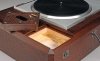
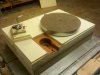
Today's progress: An arm board with space under it:
(I'm not proud)

attachment.php


attachment.php
 

Attachments

  • Plinth Build 44.jpg
    Plinth Build 44.jpg
    102.3 KB · Views: 1,126
  • Plinth Build 42.jpg
    Plinth Build 42.jpg
    99.4 KB · Views: 300
That is super nice looking.Good craftmanship.What kind of tone arm is that.How did you determine where to mount it?At this rate you will be spinning tunes soon.
Dave
 
That is super nice looking.Good craftsmanship.What kind of tone arm is that.How did you determine where to mount it?At this rate you will be spinning tunes soon.
Dave

Thanks Dave. I think the pictures make it look a bit nicer than it does in real life. I'm thinking of ways to square the outside walls without cutting them back. I found the really "drifted" during glue-up.

The arm I found cheap. It's from a Pioneer PL-51. I determined the mounting distance over at Vinyl Engine. The arm's effective length was listed in the specs for the PL-51. Then I used their arm spec calculator to find the mounting distance. (202.14 mm spindle to pivot)

All I need to do now is wire it up w/ a set of patch cords!
 
Last edited:
Back
Top Bottom