• Please note that Audiokarma will be offline briefly for updates early on Monday morning, September 28th.

Relay not clicking/engaging in a Marantz 2325

angelaudio

Super Member
I got this Marantz in non-working condition.

The speaker relay does not click therefore I am getting no sound from the speakers or the headphones. I did a little searching on AK and found this thread:


I found an issue at step 1 of post #4. Checking the voltage at J809 yielded a 60.9V reading. J808 yielded sporadic and unsteady readings from -6 to +7mV occasionally and briefly showing around 0mV. According to the thread and post I referenced above, if I am getting more than 100mV then I would need to find out where it is coming from.

So, fellow AK’ers I need help figuring out what to do next. I am an amateur and unfamiliar with the 2325 so I have no idea where to begin. I do have a multimeter, oscilloscope and a variAC so I am ready to start troubleshooting. Many thanks.
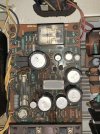
IMG_2617.jpeg

-Ernie
 
Register to hide this ad
J809 is the left channel. Disconnect the plug at the bottom of the left channel amp board then power it up to see if it comes out of protection.

One or more of the output transistors may be shorted.

If it does then you've narrowed the problem down quite a bit.

You should also have a dim bulb tester to use while troubleshooting.
 
J809 is the left channel. Disconnect the plug at the bottom of the left channel amp board then power it up to see if it comes out of protection.

One or more of the output transistors may be shorted.

If it does then you've narrowed the problem down quite a bit.

You should also have a dim bulb tester to use while troubleshooting.
I disconnected the plug at the bottom of the left channel amp board and fired it up. I left it on for about 15 seconds but got no click from the relay. I’ve been meaning to build a DBT, I think I’ll put it that together before I continue testing. What wattage bulb would be good to use on this 2325?
 
So you are looking for a voltage source of at least 60.9V, probably the +ve voltage rail. Suggest diode test output transistors, also ask mod to move thread to marantz sub forum.
So 60.9V is fine at j809? And if the output transistors diode test bad what could have caused that? I know one time I blew the OPT’s on one channel of a Soundcraftsmen amp by accidentally touching the speaker wires together, but in what other instances can the OPT’s become blown?

How do I contact the mod to move the thread?
 
Last edited:
So 60.9V is fine at j809? And if the output transistors diode test bad what could have caused that? I know one time I blew the OPT’s on one channel of a Soundcraftsmen amp by accidentally touching the speaker wires together, but in what other instances can the OPT’s become blown?

How do I contact the mod to move the thread?
No, that voltage at J809 is not good. Pull and check the output transistors for shorts. Something upstream may have failed that took them out.
 
With the amp board still unplugged do you still measure 60.9v at pin J809? There should be 0v there.

Was the correct one unplugged?

To have this moved to the Marantz forum just click on the report link at the bottom left of your post and ask to have it moved there.
 
No, that voltage at J809 is not good. Pull and check the output transistors for shorts. Something upstream may have failed that took them out.
I pulled the molex off the Right amp module and took readings and I was still getting 60V on J809, then measured J808 and got 43V. First time I turned it on with Left power module disconnected I did hear a faint click from the speaker relay.

After doing the above I shut the 2325 off and disconnected the Left amp module, powered it up and got no relay click. I measured J809, J808 again and am getting a reading of zero.

Another interesting thing I noticed is that when both amp modules are disconnected my transformer hums very faintly. When the amps are connected, I do not get that classic x-former hum.
 
Last edited:
Pull and check the output transistors. Keep track of which ones were bad so you know where to start back-checking parts in that circuit.
 
I compared some resistors against the SM and found some differences (red). Double check with the other side, maybe it was an update?

1723592792135.png
 
I compared some resistors against the SM and found some differences (red). Double check with the other side, maybe it was an update?

View attachment 3273411
Good eye, thank you. I’ll check the Other channel and see if they match. Could potentially have been an update on a later run, or maybe the SM is for earlier serials? Could be either or maybe an error in the SM? After reading about errors in Sansui SM’s, makes me wonder if Marantz did the same.
 
All the output Transistors are measuring fine on the left and right channels. So now we move backwards through P700, correct?
 
Last edited:
Please check it with your Ohm meter.
The transistor, H708, could be bad and have an emitter to collector short.
Here is a potential path to get the 60V to J809 if there is a short.

1723615111156.png
 
I am getting 1.5 megOhms from emitter to collector which positive test lead on emitter, and 7.7 megOhms with positive lead on collector
 
I mistakingly took a resistance reading. I’ll go back in and do a diode function test.
 
Last edited:
With the positive lead on the emitter and negative on collector diode function test shows .56V, with leads reversed it shows OL
 
With the amp boards disconnected I went back in to check the voltages at J809,J808 and for the right channel I am getting ~150mV, left channel right at around 0mV
 
Last edited:
Back
Top Bottom