• The move to the new server is done. There are some software and database maintenance updates in process. This has us passing the hat around to help out. We appreciate any donations. Seriously, even a dollar helps. The payment page may be found here - https://www.audiokarma.org/support.html

Relay not clicking/engaging in a Marantz 2325

I just noticed that J809 runs to the right side board (when looking at the receiver from the front). So is that the left channel or the right channel?

Edit: J809 is in fact running to the Left channel. I incorrectly assumed that the board on the right was the right channel but it’s not.
 
Last edited:
With the board that is on the left side of the receiver (when looking at it from the front) which is hooked up to J809 is connected and the right side board (J809) is disconnected at the molex and rca, I get a J809 reading of ~6.7mV. And ~7.5mV at J808. So I was checking the wrong board the whole time. I am still not getting a relay click though.
 
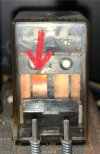
With the board on the left side back in and right power board out completely, I powered on the receiver and played some music through the aux input. I connected a speaker to the “Right” speaker input and got some extremely low sound output. When I powered off the receiver I noticed that the relay made a faint click so I powered it back on and noticed that the relay moves very slightly and slowly after a few seconds but does not make a clicking sound. I recorded a video that can be seen here to demonstrate what the relay is doing:


The first movement you see in the video is from when I turn the receiver on. Second slight movement is when the receiver is turned on. Final movement is when it is turned off again.

As you might have noticed, the second copper tab from the left does not seem to be moving much if at all. The other three tabs display visible movement.
 
I used an aux cable to go straight to “Main In” and the volume is still low. I was reading another thread about a guy who had a weak channel and traced it down to a bad BA312 IC on the PE01 preamp board, so can I rule that IC as the culprit since I already went into the “Main In” and essentially bypassed the PE01 board? I should add that the volume was higher when I didn’t go straight to the main in and just used the auxiliary input.
 
Ran pre-out to another amp and it worked like a charm. So I’m guessing PE01 is fine. Still I removed it and cleaned the pins on the connector on PE01 as well as the Tone selector, tone pots, and volume pot. Ruling PE01 out as the source of any issues.
 
H708 is fine on the left channel. All readings within acceptable range.
IMG_2673.jpeg

Which component should I check next?

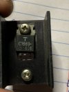
Is this a Relay Driver transistor? Echowars, in his old transistor thread mentions that he always changes RDT’s because “…gain eventually droops to the point where it can no longer close the relay.”
 
Last edited:
Bump. Wondering if that 2SC1669 should be changed out even though it passed the diode test on my multimeter. Should I put the board back in circuit without it and see if I am still getting 60V at pin J809?
 
Last edited:
With the board that is on the left side of the receiver (when looking at it from the front) which is hooked up to J809 is connected and the right side board (J809) is disconnected at the molex and rca, I get a J809 reading of ~6.7mV. And ~7.5mV at J808. So I was checking the wrong board the whole time. I am still not getting a relay click though.
What is the voltage across the L801 relay coil (diode H12) when you did this test? Is it 24VDC?
With that melted relay and bent contact, maybe caused by the 60V going through the relay from the failed P700 board. Is the bad contact on the same channel as the measured 60V? I would think the first thing to do is replace it.
 
What is the voltage across the L801 relay coil (diode H12) when you did this test? Is it 24VDC?
With that melted relay and bent contact, maybe caused by the 60V going through the relay from the failed P700 board. Is the bad contact on the same channel as the measured 60V? I would think the first thing to do is replace it.
Voltage across H12 is 24.96VDC.

I will check to see if that bad contact on the relay is on the same channel (Left) as the 60V at J809.
 
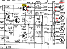
Here is tracing the path on the PCB and schematic for the burned out contact.
When you have the 60V on J809, the protection circuit won't energize the relay so the voltage will not go to the speakers.
So, it looks like at some point the 60V did go through the relay contacts and possibly damaged the contact arm.
1723772789700.png

1723772819064.png
 
When you previously measured the resistance (diode test) between H708 collector and emitter were the output transistors H001 & H002 installed or removed?
A base to collector short of either of the two could also show up as the 60V on J809.

1723776698897.png
 
When you previously measured the resistance (diode test) between H708 collector and emitter were the output transistors H001 & H002 installed or removed?
A base to collector short of either of the two could also show up as the 60V on J809.

View attachment 3275012
When I first measured H708 it was in circuit and H001/H002 were installed. The second time I measured H708 it was removed from the circuit. I desoldered it from the the PCB.

Base to collector readings on the transistors were all OL. I will check again just to make sure. Does the positive test lead go on the base?
 
Base to collector on H708 is showing up as .56V

Base to collector on H001, H002 with negative lead on the base is giving me .49VDC on one and .51VDC on the other
 
Base to collector readings on the transistors were all OL. I will check again just to make sure. Does the positive test lead go on the base?
Base to collector on H001, H002 with negative lead on the base is giving me .49VDC on one and .51VDC on the other
Grabbed this from the internet on how to test a transistor with a multimeter... maybe this helps.
H001 & H002 are both PNP transistors. H708 is an NPN.

1723787350642.png
 
I am getting sound from the Right channel but it is very low both through the headphone Jack and the speaker terminals. Is it possible that the relay is engaging but only allowing weak sound to come through due to the damage that was done by the 60V on the left side of the relay?
 
I’ve been meaning to build a DBT, I think I’ll put it that together before I continue testing.
Now is the time to build and use a DBT so we don't damage any boards. Did you build one?
You said that you have an oscilloscope. Do you know how to use one? If you do, then you can check for the audio signal before it gets to the relay, then after the relay.
 
Last edited:
Back
Top Bottom