angelaudio
Super Member
Yes I put one together yesterday, I have a 100W incandescent bulb in there.Now is the time to build and use a DBT so we don't damage any boards. Did you build one?


Yes I put one together yesterday, I have a 100W incandescent bulb in there.Now is the time to build and use a DBT so we don't damage any boards. Did you build one?

I just noticed that J809 runs to the right side board (when looking at the receiver from the front).
With the board that is on the left side of the receiver (when looking at it from the front) which is hooked up to J809 is connected and the right side board (J809) is disconnected
Sorry, can you please clarify this for me:With the board on the left side back in and right power board out completely, I powered on the receiver and played some music through the aux input.
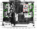
J809 runs to the power amp board that sits next to P700, which is the Left channel. When I was first troubleshooting, I incorrectly assumed that the board on the left hand side of the receiver (when looking at it from the front) was the left channel, but that is actually the Right channel board. It seems counterintuitive that the Left channel board is on the right side of the receiver next to P700 but that’s the way it is wired in my 2325, not sure if it’s reversed in other 2325’s. In this picture I have the bad Left channel board out, while the Right channel board is in.Sorry, can you please clarify this for me:
View attachment 3275277
- J809 has the 60v on it.
- The schematic shows it is connected to the R-channel P700 board .
- Your first statement says that J809 goes to the right side board when looking from the front.
- Then you said, J809 is connected to the P700 board on the left side of the receiver (looking from the front) and connected to J809
- Can you please clarify, so we are on the same page? The problem is with the R-channel and the P700 board is located on the right of the chassis looking from the front?
Yes I just recently picked up a Tektronix 2246, which I haven’t learned how to use yet but Blueglow electronics has the same scope and a few YouTube videos where he explains how to use it so I’ll be watching those very soon so I can monitor the signal in the spots that you mention.Now is the time to build and use a DBT so we don't damage any boards. Did you build one?
You said that you have an oscilloscope. Do you know how to use one? If you do, then you can check for the audio signal before it gets to the relay, then after the relay.
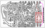
R Chan. = Good
L Chan. = Bad
You can try to bypass the relay contacts to see if audio gets through the relay to the output terminals for the good, R-channel.
Do this with the bad L-channel board disconnected.
First, make sure that the voltage on J808 (R-chan) is still close to 0V.
Next, with power off, connect a jumper from J808 (output of R-chan P700) to J810 (R-chan speaker terminal), bypassing the relay contact. (violet line on diagram)
Turn volume knob to minimum.
Turn-on power, slowly turn up volume control, and check to see if you now get volume at the R-chan speaker output.
If you get good volume, then the relay is bad, otherwise we look elsewhere.
View attachment 3275311
And since I have had success with the pre-out into another amplifier, I can safely assume the pre-amp section is OK as well? I would like to recap it eventually but first want to get the P700’s sorted out and go from there.If you measured the output voltages on P800 and they were OK, then most likely not the problem.
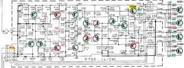
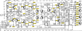
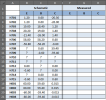
Sorry I forgot to mention, the voltages I measured are for the Right channel, the one that is currently working but has low volume. I will plug the Left channel power amp board in tomorrow and list the voltages. Sorry for the confusionOK, I transferred your measured voltages onto the Left CH P700 board schematic. Green is good, red is not quite good voltage.
If I remember correctly, you previously had a problem with 60V appearing on the P800 Power Supply board that would cause the relay not to engage.
View attachment 3276871

Confusing. You are currently trying to fix the right channel board, which has a low volume and @dankik is trying to resolve the issue if it is a relay or a p700 board problem. So why are you trying the left channel, stick with the right channel for the test until we know the issue. @dankik is taking you through the process step by step, stick to it and the right channel, leave the left channel board out for the moment.Sorry I forgot to mention, the voltages I measured are for the Right channel, the one that is currently working but has low volume. I will plug the Left channel power amp board in tomorrow and list the voltages. Sorry for the confusion
Cool. No offense intended, trying to help, I suggest sticking to the right channel for now, and then once sorted out, move to the left, if we get that right channel working, then the power and relay would also be fixed in the process. The left has -+60V, so debugging can create issues ATM. Keep the left out until the right is sorted out.@GRonald Yes I am very grateful for @dankik offering his very methodical and thorough guidance on this issue, there was a bit of confusion on my end regarding what channel because I got a little caught up in why the Right channel volume was so low, but I’m back on track and going to take readings of the Left channel moving forward. I have around ~6mV on J808, 60V at J809 and will measure J810/811. I’ll check the resistors you mentioned as well, I appreciate you chiming in, thank you.