• The move to the new server is done. There are some software and database maintenance updates in process. This has us passing the hat around to help out. We appreciate any donations. Seriously, even a dollar helps. The payment page may be found here - https://www.audiokarma.org/support.html

Relay not clicking/engaging in a Marantz 2325

H707 Diode test:
B-E=.69V
B-C=.677V
E-B, C-B, C-E = All OL

H706 Diode test:
E-B=.688V
C-B=.658V
B-E, B-C, C-E= All OL

Can these transistors all be testing fine but have leakage that is not detectable with the diode function test?
 
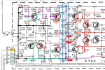
Can you please check transistor H705. It looks like it is not turned on so the collector voltage is the same as H704, which is forcing the common point also to 20.7v vs 1.4v.

1724871063996.png
 
Just realized my multimeter has an HFE function so here are some readings:

H704: 147hFE
H706: 92hFE
H707: 121hFE


I will check H705 and report back shortly.
 
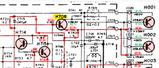
H708 tested fine:

B-E=.57V
B-C=.56V
E-B, C-B, C-E= All OL
708 is conducting fine. did You check 709?
The one way to know if 704/705 are conducting and the voltage reading are not right due to the 709 not conducting is to desolder one leg of R721 (270 Oms) and then measure voltages at pins of 704/705.
There is a high possibility that there is a short on the H001 or 709 not conducting or having a problem, bringing +60 volts, which is affecting the voltages readings on the other transistors (704/705).
There is a 100K resistor R729 dropping the voltage from +60 to approx. 10V to the base of 702. and so are other resistors dropping the voltage at the collectors of 704/705. if 704/705 were not conducting the voltage readings would be different. The reading point to problem with the driver/output's stages and not the early stages.

Also note there is a capacitor c704 inline (to the high +60 v coming from the output stage) which goes to the collector of 703 and emitter of 701/702 and that is why the voltages are ok as the capacitor is blocking the DC, again, indicating a problem with your driver/output stage.
Can you post a picture of the board PCB side and the heatsink so we can see the transistors, hopefully you have them in correctly.
 
Last edited:
Did you ever pull and test H001, H002, H003, & H004?
I did at the very beginning but I will pull and test again just to make sure.

@GRonald yes 709 tested fine:
B to E = .584V
B to C = .572V
E to B = OL
C to B = OL
C to E = OL

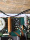
And I will get that picture to you after dinner. I have to put a few transistors back in, as I had pulled them for testing. Before pulling any transistors the board appeared untouched, so the +60V on J809 was present before I went in and desoldered anything. Here’s a picture of before:
IMG_2624.jpeg
 
Last edited:
And all were in their correct NPN/PNP positions in the heatsink with mica insulators (no shorts to heatsink)?
 
And all were in their correct NPN/PNP positions in the heatsink with mica insulators (no shorts to heatsink)?
Yes all were in the correct positions, with mica insulators and no shorts to the heat sink. I will reassemble the board and reinstall to see if there are any changes.
 
I just resoldered everything I had pulled and reinstalled the power board. Still have 62V on J809 and J808 reads 45V, without the Right channel power board installed.
 
I just resoldered everything I had pulled and reinstalled the power board. Still have 62V on J809 and J808 reads 45V, without the Right channel power board installed.
1. Right, can you take R721 (270 Ohms out) and test the voltages on Q704/705.
Note: this is important to determine where the problem is originating from. If you could please do this.
I still want to see a picture of the Transistors mounted on the heatsink.
2. Also, can you check and let us know the transistors installed in 703/704/705 (just need to make sure the right npn/pnp are in})
3. I am going to pull the p700 out today from one waiting for a restore and we can do a dry resistance test at crucial points in the output stage.
 
Last edited:
1. Ok can you take R721 (270 Ohms out) and test the voltages on Q704/705.
Note: this is important to determine where the problem is originating from. If you could please do this.
I still want to see a picture of the Transistors mounted on the heatsink.
2. Also, can you check and let us know the transistors installed in 703/704/704 (just need to make sure the right npn/pnp are in})
3. I am going to pull the p700 out today from one waiting for a restore and we can do a dry resistance test at crucial points in the output stage.
For step one, what is Q704/705?

2. H703=2SA722, H704=2SA720, H705=2SC1318

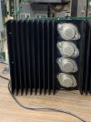
Here are the output transistors:
IMG_2940.jpeg
 
Back
Top Bottom