

You are using an out of date browser. It may not display this or other websites correctly.
You should upgrade or use an alternative browser.
You should upgrade or use an alternative browser.
Restoring a Sansui AU-X1
- Thread starter wmac
- Start date

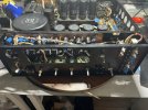

My amp serial number is 220080021. It refers to August 1980 and is the 21st unit produced that year. Now, my question is about the Flat-Amp: there are 2 Black Flag capacitors installed, marked 4pF (C15 and C16), but in the manual, they are 3pF. The manual had a factory revision, so it doesn't match what is installed. I replaced them following the manual.

Generally you should work with what is in your unit now, NOT the manual. Your manual never had to work to spec as a functioning amplifier, your X1 with component values (as it left the factory) and 'as found' did, apparently for years.replaced them following the manual

In this particular case, as the value difference is so small, it shouldn't matter, buy hey, its an AU-X1 (Ultra High Speed DD/DC)

Last edited:
Thank you for all the informationGenerally you should work with what is in your unit now, NOT the manual. Your manual never had to work to spec as a functioning amplifier, your X1 with component values (as it left the factory) and 'as found' did, apparently for years.
In this particular case, as the value difference is so small, it shouldn't matter, buy hey, its an AU-X1 (Ultra High Speed DD/DC)
 regarding the 2 black flag caps. They were installed after, in the back of the board, so that I may have mistaken them for C15/16 with those caps; they are not listed in the manual.
Last edited:
My statement is wrong, the ones that were installed in the back of the board were 2pF, and I replaced them with the same value, now the 4pF were in fact the C15/16 that I replaced with 3pFThank you for all the information
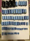
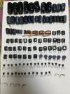

I need some help: 2 grey cables come from the power supply and go to the driver boards. Their positions on the power supply are pin 12 and pin 13. They will connect to the board F-2775 at position 16 on each side, but I am not sure whether 16 is the correct one; the schematic is not clear. I would appreciate it if somebody had the picture or could tell me if pin 16 is the right one.
Thank you
Thank you

Thank you, by the way, do you have his URL? I can not find him here.I’m sure that someone is going to chime in here but in any case you can visit “amp 8” website with lots of high resolution photos.
Especially in AU-X1/X11 the “B -series “ and many others , he has a huge collection of restorations following high resolution photos .
I think you'll find its F-2775 pin12 (R) and pin12 (L) that are the output lines going from F-2775 (R & L) to the output switching relays and protection circuit on F-2781. Pins 12 & 13 on F-2781 are the other part of the protection circuit, using sensing lines from F-2775 pin16 (R & L).I believe I figured out that F-2781 pins 12 and 13 are the left/right power amp output lines going to the protection/speaker relay circuit, and should connect to Pin 16 at the F-2775.
Well, after putting all back, set the DC Offset and Bias, I can not produce sound, the speaker relay will not click, I measured the DC Offset before the relay between pin 16 and ground, and I have 0.3 mV, the relay should engage, I believe that I still have a problem with the protection circuit, I will check. 
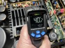
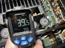
The problem was in the protection circuit. took some time because I was waiting for parts, then I decided to work on a Trio KP-5050, which is already ready.So what was the problem ? Post#73
Similar threads
- Replies
- 14
- Views
- 9K

- Replies
- 17
- Views
- 2K

