• The move to the new server is done. There are some software and database maintenance updates in process. This has us passing the hat around to help out. We appreciate any donations. Seriously, even a dollar helps. The payment page may be found here - https://www.audiokarma.org/support.html

Restoring a Sansui AU-X1

I'm not 100% sure but I believe the reason for this capacitor (from collector to base) is to reduce RF gain of the driver transistor. Either here or in a power amp. With long wires and traces you create tuned circuits that could make a transistor in this position an oscillator because its f(t) is usually way above 100 MHz. So 91 pF is as good a value as 100 pF. Why Sansui chose an E24 value? Maybe they just had many in stock. Stability in amps is always a bit of voodoo. Especially when they sometimes exhibit destructive oscillation. But the X1 only does that if the black flags in the power output go phut.
 
I am doing the MM and MC boards, but I had to stop until I receive the MLCC that will take another 10 days to get here.
 
I just bought several ceramic caps COG to replace these ones, but I am confused, in the F-2917 and F-2918, it shows a 30pF capacitor in the parts list, the black ones, but installed on the board, I have the 91pF. I will go with the value that is installed.
This manual is a mess.:eek::wtf:
Go with what is in your amp had the same problem the unit different to schematic
 
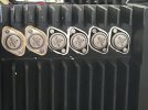
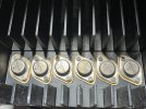
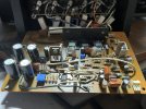
One channel driver, and outputs are out, just testing and cleaning the output transistors. If you note in the picture, they are series "N", they have some kind of silver coat, and they are tarnished, now testing and cleaning them one by one.

IMG_2441.jpg
 
Drives and output are done from one side, now I will start on the right side

IMG_2451.jpg

All back-flags are gone, all Caps replaced, trimpots replaced, and transistors and other components have been tested,
 
I think I can see original Fuse Resistors on that board (R36 & R37, 390Ω) - they really need to be replaced even if they test good, which I doubt they will.

They are not marked on the schematic as fuse resistors, even though the schematic legend includes 'fusing resistors', all of mine were effectively 'open'.
 
Last edited:
I think I can see original Fuse Resistors on that board (R36 & R37, 390Ω) - they really need to be replaced even if they test good, which I doubt they will.

(They are not marked on the schematic as fuse resistors, even though the schematic legend includes 'fusing resistors', all of mine were effectively 'open'.
Thank you for the heads up. I will address them.
I have another problem, I can not remove the volume knob, the screw is locked in place, and it is an allen 1.5mm. If I force too much, I can break the tool inside, and it will be a pain to remove. I thought to heat the knob once it is aluminum and the screw is steel, but I am concern to change the aluminum color. I would be glad to have some suggestions.
 
I can not remove the volume knob, the screw is locked in place

That's a tough one, I would resist heating the knob in favour of further tries to release the Allen set-screw.

Is it possible that someone used thread lock on the screw? - I hope not. I think I would try some penetrating oil? - and perhaps heating just the tip of the Allen key - to as hot as practical, before trying to loosen the screw. - I like this last thought particularly as it has the potential to get 'heat' right where it is needed (to break friction or 'thread lock' usage) without risking damage to the volume control or the rest of the amplifier.

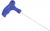
I have an extra long correct size Allen key with a 'T Bar' top - for maximum twisting power, simple 'L' shaped Allen keys don't have much 'crank' length to assist with twist power, for loosening or tightening.
 
Last edited:
That's a tough one, I would resist heating the knob in favour of further tries to release the Allen set-screw.

Is it possible that someone used thread lock on the screw? - I hope not. I think I would try some penetrating oil? - and perhaps heating just the tip of the Allen key - to as hot as practical, before trying to loosen the screw. - I like this last thought particularly as it has the potential to get 'heat' right where it is needed (to break friction or thread lock usage) without risking damage to the volume control or the rest of the amplifier.
Thank you, I don't believe that thread lock was used because the other knobs were tight but not difficult to remove, the volume knob is 50 mm in diameter, and the screww was seated at 30mm. You're right, it will be some tough to get it out, and if I can not do it, I can not remove the front face
 
it will be some tough to get it out, and if I can not do it, I can not remove the front face
Yes, that's right - a bit of a show stopper.

Let us know how you get on, this should be do-able. :thumbsup:

1777451588724.png
This is my one - you'll have to limit the heating with this style of Allen key as you will possibly melt the plastic handle!

Perhaps use a standard 'L' shaped one for the heating effect? - and then follow up with the 'bad boy' in the picture. :)
 
Last edited:
Yes, that's right - a bit of a show stopper.

Let us know how you get on, this should be do-able. :thumbsup:

View attachment 3752043
This is my one - you'll have to limit the heating with this style of Allen key as you will possibly melt the plastic handle!

Perhaps use a standard 'L' shaped one for the heating effect? - and then follow up with the 'bad boy' in the picture. :)
Thank you, I have only the standard allen tool. I will buy one set of those T-handle
 
I need more help with the MC boards F-2917 and F-2918. The manual says the trimpot should be 100 Ohms, but I removed the pot from the boards and measured 250 Ohms. However, the case is that the solder does not look like it was installed by the factory. Can somebody confirm if it is 100 or 250 Ohms?
 
Can somebody confirm if it is 100 or 250 Ohms?
Either. In case of 250 ohms you could change R35 to 470 ohm to get the adjustent range more centered. I think this is an offset adjustment. With the output caps this is not really a necessity. Manual to confirm the function of VR01.
 
Back
Top Bottom