• The move to the new server is done. There are some software and database maintenance updates in process. This has us passing the hat around to help out. We appreciate any donations. Seriously, even a dollar helps. The payment page may be found here - https://www.audiokarma.org/support.html

Rotel RA-1412 Restoration Project

richiem46

Retired and enjoying life and music!
Subscriber
Through a series of recent events I find myself the owner of a Rotel RA-1412 integrated Amplifier. Based on my research it is an excellent amplifier with a few quirks. I have not received the unit as of yet but apparently the right channel is out. It has been in one family for it's entire life so has been well looked after.

The maintenance manual looks pretty good but the parts list included in it does not list the capacitors which surprised me. It will need a re-cap for sure but I have not found a "parts list" for the 1412 that include the caps. If anyone can point me to additional resources I would appreciate it. There is a "kit" on the bay with all of the caps which I am considering purchasing but will wait a bit to see what else may be needed.

I should receive the unit by the end of the week and will post information on my progress in restoring it. After I complete it I will offer it to the present owner for the cost of the parts used in it's restoration.

Looking forward to the new project!

rotel-1412 pic.jpg
 
Register to hide this ad
I did a small job on a RA-1412, nice build, impressive sound, hope you also like it.
I'd stay away from the ebay kits, make up your own BoM and buy from mouser/digikey/..., certainly do a serach on AK.
 
I am leaning towards making up my own list. I have a bunch of electrolytic and other types of caps on-hand that I accumulated restoring Marantz receivers. I think I will wait until I receive the Rotel so I can confirm the pinout before ordering the relay. I was considering using screw-terminal caps for the four main caps but am not sure how much headroom the chassis has. Again, once I receive it I can determine the dimensions I have to work with.

Thanks everyone for the feedback, I appreciate it!
 
  • Like
Reactions: mbz
I received the Rotel Yesterday and started going over it. The left side of the front panel is bent a bit by the rack mount handle. It apparently occurred during shipping but the box looked fine and the unit was well padded. Oh well......

PXL_20230128_192121043.jpg
 
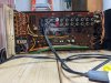
I powered it up gradually with a variac and it came out of protection without issue. The left channel played well and right channel did not play at all. I decided to try bridging the pre-in and pre-out with a patch cable. the right channel played well when I patched it to the left pre-out but not when patched to the right pre-out. So it must be the right pre-amp....... But no......

I worked the unite-separate switch back and forth and after several cycles and some wiggling low and behold the right channel began to play well. I figured I would disassemble the pre-amp in board and inspect and thoroughly clean the switches and RCA jacks to hopefully fix the problem.
 
I started to remove the screws that secure the panel over all of the input/output jacks and switches. About half of them came out without issue but the remainder will not budge. I have applied WD-40 repeatedly and waited several hours but no luck so far. I ordered a #1 and #2 JIS screwdrivers figuring maybe they would work better as the Rotel was made in Japan. I also ordered a VMAN damaged screw extractor in case things call for more drastic action.

PXL_20230129_201851537.jpg

If anyone has suggestions as how to best proceed I would appreciate any input!
 
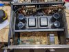
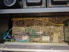
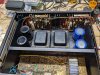
Here is a picture of the inside of the Rotel. It needs a good cleaning for sure, as does the front panel.

PXL_20230129_201933802.jpg

PXL_20230129_202041589.jpg
 
I am leaning towards making up my own list. I have a bunch of electrolytic and other types of caps on-hand that I accumulated restoring Marantz receivers. I think I will wait until I receive the Rotel so I can confirm the pinout before ordering the relay. I was considering using screw-terminal caps for the four main caps but am not sure how much headroom the chassis has. Again, once I receive it I can determine the dimensions I have to work with.

Thanks everyone for the feedback, I appreciate it!
I used screw terminal ones. They work just fine. I made a connector out of 12gauge solid wire with an eyelet on each end to jump the cap pairs together, the ground if you will. Soldering to that was easy afterward.
 
Last edited:
I used screw terminal ones. They work just fine. I made a connector out of 12gauge solid wire with an eyelet on each end to jump the cap pairs together, the goround if you will. Soldering to that was easy afterward.

I will do something similar, will look in our junk closet for some 12G wire or head to the hardware store tomorrow.
 
I received the extractor kit yesterday and it also contained JIS #1 and #2 screwdriver bits. I tried them on the frozen screws and the #2 fit quite securely compared to the regular phillips screwdriver I had used previously. I tried the first screw and was able to apply more torque without the bit slipping and happily it cracked free! I tried all of the remaining screws and was able to remove all but one of them. I used the extractor drill and bit on the remaining screw and was able to successfully remove it. Suffice it to say I was quite pleased! I cleaned and lubricated the three switches and they now work well, no sticking and no faulty connection issues.

I am attaching a picture of the board below:

PXL_20230131_134505956.jpg
 
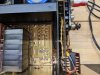
While I was waiting for the extractor set and other tools to arrive I started cleaning the circuit boards as they are coated with a yellowish sticky substance. I am guessing nicotine stains but may be wrong. I used 99% isopropyl alcohol to clean the board with cue tips. A bit tedious but it looks much better and I figured the "goop" could potentially be a problem going forward. I am attaching a picture of the section I cleaned and on of a smaller section I have yet to clean for comparison.

PXL_20230131_134555350.jpg

PXL_20230131_134602217.jpg
 
Last evening I started replacing the four main filter capacitors as I already had them on-hand. I did the right channel first and used screw terminal capacitors for replacement, 22,000 UF 80V. The installation was pretty straightforward and went without issue. I will do the Left channel power supply today.

PXL_20230131_134543351.jpg
 
Since the amplifier is working well at this stage I am pondering how much more I want to refurbish it, remembering the maxim "If it Ain't broke...". I generally make a point of replacing most of the electrolytic caps as after 50+ years it seems prudent. I will also replace the protection relay as that also is generally a good idea after 50 years. Some of the research I have done indicates components on the power amplifiers can be problematic on this model of Rotel so I will probably replace some of the small transistors with matched replacements as well as the electrolytics on the power amps. I am attaching a picture of pne of the power amp boards. It is quite dirty and some of the thermal compound looks like it has seen better days. After I finish work on the protection and power supply boards I will decide how much I want to do to the power amps.


PXL_20230131_134621549.jpg
 
Since the amplifier is working well at this stage I am pondering how much more I want to refurbish it, remembering the maxim "If it Ain't broke...". I generally make a point of replacing most of the electrolytic caps as after 50+ years it seems prudent. I will also replace the protection relay as that also is generally a good idea after 50 years. Some of the research I have done indicates components on the power amplifiers can be problematic on this model of Rotel so I will probably replace some of the small transistors with matched replacements as well as the electrolytics on the power amps. I am attaching a picture of pne of the power amp boards. It is quite dirty and some of the thermal compound looks like it has seen better days. After I finish work on the protection and power supply boards I will decide how much I want to do to the power amps.


View attachment 2784469
If it aint broke....... it will break.

This is a 50 year old piece of electronics. Preventative maintenance is needed.
Those transistors with the thin metal tab in the middle of the top of the amp board need to go. KSC3503 and KSA1381.
Be sure to replace those yellow caps with Nichicon KL.
Bourns 3386H should work for the trimmers.

Looks like it needs a bath.
 
I have all the transistors on hand to replace pretty much all of them in the unit. I figure of I am going to clean up the heatsink compound I might as well replace the transistors while I am at it. Just have to psyche myself up!
 
Back
Top Bottom