

You are using an out of date browser. It may not display this or other websites correctly.
You should upgrade or use an alternative browser.
You should upgrade or use an alternative browser.
Rotel RA-1412 Restoration Project
- Thread starter richiem46
- Start date


I went through my substitutions and their lead designations as a sanity check to see that the substitutes I used were correct and that I got the leads straight also. I then removed the board again and physically verified that all the transistors were installed in the proper locations with the leads in the correct orientation.
Here is a little spreadsheet I put together to keep things straight.
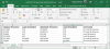
Here is a little spreadsheet I put together to keep things straight.
After confirming that the components were in order I re-installed the board and tested the amp again hoping to isolate what the issue was. Before powering it up again I adjusted VR601 on the new board to match the setting on the good left channel to hopefully get the DC offset near where is should be having read in the manual that the offset being way out could trigger protect mode. I hooked the meter to the repaired power amp to monitor DC offset and then gradually powered up the amp with the variac. The DC offset was all over the place but then suddenly "snapped in" and settled down to about .04V. At about 63VAC the amp came out of protection and played normally. I gradually increased the A/C voltage tp about 100VAC and the DC offset regulated itself as I increased the A/C. Then suddenly the amp went into protection and the DC offset jumped to about 24V which I assumed is what triggered protection. I left the amp in protection and (not very scientifically) tapped the board here and there and pressed on the exposed edge. Suddenly the DC offset reset to about .04V. I power cycled it to reset protection and the amp played again but quit after a few minutes. I figured that I had a suspect connection and so touched various components with a plastic tool and when I touched Q606 DC offset snapped back to a normal level.
At this point I shut everything down and called it an evening figuring I would remove and work on the board the next day.
At this point I shut everything down and called it an evening figuring I would remove and work on the board the next day.
Today I removed the board and inspected Q606 from the underside. There was nothing obvious by visual inspection so I decided to remove the transistor entirely to be sure I did not miss anything. After removal I could see that the foil around the center lead (C) was partially missing. I installed a new transistor so I could have more lead length and bent the center lead over the remaining foil after cleaning it and re-soldered it securely. I re-soldered the other 2 leads and re-checked the board again and then re-installed it in the amplifier.
I powered up the amp to full A/C voltage and all was well. I dialed in the bias and the DC offset and all readings held steady. I power-cycled the amp plugged directly into the A/C line and all was well. It has been playing for several hours without issue so lt looks like the amp board is good to go!

I powered up the amp to full A/C voltage and all was well. I dialed in the bias and the DC offset and all readings held steady. I power-cycled the amp plugged directly into the A/C line and all was well. It has been playing for several hours without issue so lt looks like the amp board is good to go!

While restoring the right amp module I discovered several things. The module had been previously repaired with one of the drover transistors being replaced with a ECG292 and the other was the original C1624. They were replaced with a MJE15032/33G pair. I tested the old driver transistors and the ECG292 tested good while the C1624 gave me some odd readings which I interpreted as a failing transistor. Here are a few pictures of the readings I got.

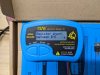
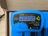
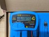

No surprise there.
I also tested the four output transistors from the right channel and three of them had HFE values around 80 while one of them had an HFE value of 8. They had been replaced previously and I replaced them all with MJ21194G transistors.
The amplifier worked before I restored the right power amplifier but I took no power measurements nor did I attempt to align the watt meters per the manual as I figured it made sense to wait until the power amps were restored and then perform that alignment. I thing the amp is playing a bit stronger now than before I restored the module. The right amp heat sink barely got warm before I did the restoration while the left heat sink got warm after playing for a while. After the restore the right amp now also gets warm after playing for a while. Not very scientific but an indicator it is dissipating more power.
Overall the sound of the amplifier has improved considerably since I started restoring it. I can see why some folks are really fond of the sound of Rotel gear. The amp is really pleasant to listen to.
I have to decide now if I am going to replace the Original Toshiba output transistors on the left power amp when I restore it. I will test them when I remove them of course. I am leaning towards replacing them as I have the MJ21194G transistors on-hand and I will have it apart. That project will be simpler as I have experience now with the right module so know what to expect when restoring the left.
The amplifier worked before I restored the right power amplifier but I took no power measurements nor did I attempt to align the watt meters per the manual as I figured it made sense to wait until the power amps were restored and then perform that alignment. I thing the amp is playing a bit stronger now than before I restored the module. The right amp heat sink barely got warm before I did the restoration while the left heat sink got warm after playing for a while. After the restore the right amp now also gets warm after playing for a while. Not very scientific but an indicator it is dissipating more power.
Overall the sound of the amplifier has improved considerably since I started restoring it. I can see why some folks are really fond of the sound of Rotel gear. The amp is really pleasant to listen to.
I have to decide now if I am going to replace the Original Toshiba output transistors on the left power amp when I restore it. I will test them when I remove them of course. I am leaning towards replacing them as I have the MJ21194G transistors on-hand and I will have it apart. That project will be simpler as I have experience now with the right module so know what to expect when restoring the left.

In an earlier post I mentioned that two 220UF 35V capacitors in the right power supply were replaced with two 220UF 25V caps. Tonight I went to replace the 220UF caps in the left power supply which were original to the unit I found that the original caps were also rated at 25V. The schematic has these caps rated at 35V so guess the schematic is wrong or there was a change made in production.
I have started restoring the second power amp module. It is going along pretty smoothly since it is the second one for me. It is about 50% completed as of this evening and I will probably finish it over the weekend.
I removed and tested the four Toshiba output transistors from the left amp. Three of them tested with an HFE of 58-60 while the fourth tested with an HFE of 28. The service manual discusses using transistors in the same HFE "Rank" for the output transistors. The lower "Rank" of "O" specifies an HFE Range of 70-140 which none of the existing output transistors are in. The new MJ21194G transistors have an HFE of around 68 if I remember correctly, I will re-check them in the morning.
My inclination at this point is to just replace the Toshiba outputs with the MJ21194G's. The amp did play well with the Toshiba's installed but I did not perform the full power testing called for in the service manual as of yet. I guess I could re-install them and if I have problems with the full power test in that channel replace them at that point.
Thoughts?

I removed and tested the four Toshiba output transistors from the left amp. Three of them tested with an HFE of 58-60 while the fourth tested with an HFE of 28. The service manual discusses using transistors in the same HFE "Rank" for the output transistors. The lower "Rank" of "O" specifies an HFE Range of 70-140 which none of the existing output transistors are in. The new MJ21194G transistors have an HFE of around 68 if I remember correctly, I will re-check them in the morning.
My inclination at this point is to just replace the Toshiba outputs with the MJ21194G's. The amp did play well with the Toshiba's installed but I did not perform the full power testing called for in the service manual as of yet. I guess I could re-install them and if I have problems with the full power test in that channel replace them at that point.
Thoughts?

Stattman
Member
Could you possibly share a whole list of materials and their ratings that you used to restore this unit? I have an exact same 1412 with many problems and am looking to do a full restore some day when I get my skills up. Threads like these help so much even if I'm just in the planning stage.
Could you possibly share a whole list of materials and their ratings that you used to restore this unit? I have an exact same 1412 with many problems and am looking to do a full restore some day when I get my skills up. Threads like these help so much even if I'm just in the planning stage.
I will upload some documentation in a few days. I have company here now so time is limited.
I finished restoring the left power amp module last night and re-installed it in the amp. I powered the amp up via a variac with a dummy load on the left channel in case there were issues to protect the speaker I am now using. The amp came out of protection and I eased the A/C up to 115V while monitoring the DC offset and all was well. I adjusted the DC offset and the bias and then hooked up the left speaker and powered up the amp and it is playing beautifully. I warmed it up for several hours and dialed in the bias and DC offset on both channels again and all is well.
Tonight I calibrated the power meters per the service manual and also set the overload protection adjustment. For the overload protection adjustment you use a 4 ohm dummy load on the speaker terminal, feed a 100hz tone into the AUX input and adjust the signal generator input and the volume control until you read 30VAC across the 4 Ohm dummy load. I=E/R so 30V/4 = 7.5A X 30V = 225W if I am getting the math right. You then adjust VR603 until the amp just goes into protection. I was a bit nervous about operating a 125WPC amp at 225W but all went well. The heat sink on the outputs got quite warm but not alarmingly so. After making the adjustment on both channels protection now trips at 25VAC which translates to about 156W which is a bit more reasonable.
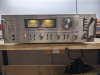
I then re-dressed the wiring and put the front panel and knobs back on as well as the rest of the case except for the top. The amp is looking quite good now. I will attach some pictures below.
Tonight I calibrated the power meters per the service manual and also set the overload protection adjustment. For the overload protection adjustment you use a 4 ohm dummy load on the speaker terminal, feed a 100hz tone into the AUX input and adjust the signal generator input and the volume control until you read 30VAC across the 4 Ohm dummy load. I=E/R so 30V/4 = 7.5A X 30V = 225W if I am getting the math right. You then adjust VR603 until the amp just goes into protection. I was a bit nervous about operating a 125WPC amp at 225W but all went well. The heat sink on the outputs got quite warm but not alarmingly so. After making the adjustment on both channels protection now trips at 25VAC which translates to about 156W which is a bit more reasonable.
I then re-dressed the wiring and put the front panel and knobs back on as well as the rest of the case except for the top. The amp is looking quite good now. I will attach some pictures below.




Oldsansui441
Super Member
Looks terrific 

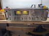
I see an epoxy diode (black/yellow) that will cause you issues in the middle right. I would measure those brown carbon composition resistors, they're normally off a lot.