• Please note that Audiokarma will be offline briefly for updates early on Monday morning, September 28th.

Rotel RA-1412 Restoration Project

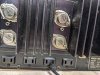
I am waiting for some parts to arrive from Mouser, they are affected by the winter weather apparently. In the meantime I took off the front panel and cleaned up the knobs and the panel itself. It all cleaned up very nicely. I removed the phono amp board and found that there was a bad ground on the AUX1 input RCA jacks. I had to remove one section containing the AUX1/2 and tuner inputs. Unsoldering and removing it was good for 90 minutes of entertainment but I got it out and was able to repair the bad ground and re-install it. I then cleaned the board with alcohol and Q-tips and it is looking much better. I can't re-install it until I receive the caps from Mouser.
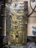
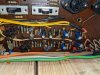
PXL_20230204_014855091.jpg


PXL_20230204_014956051.jpg
 
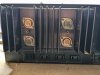
I removed the covers on the output transistors and on the left channel there are four Toshiba 2SD242 transistors and on the right are two NEC KSD555 transistors and two SK9237 transistors. I am assuming that the Toshiba's are originals and the mixed Right channel transistors are replacements. I am planning on replacing the transistors in the "Mixed" right channel with Onsemi MJ21194G transistors even though the channel is working.

Thoughts anyone?

PXL_20230204_021918455.jpg


PXL_20230204_022006834.jpg
 
I removed the covers on the output transistors and on the left channel there are four Toshiba 2SD242 transistors and on the right are two NEC KSD555 transistors and two SK9237 transistors. I am assuming that the Toshiba's are originals and the mixed Right channel transistors are replacements. I am planning on replacing the transistors in the "Mixed" right channel with Onsemi MJ21194G transistors even though the channel is working.

Thoughts anyone?

View attachment 2788675


View attachment 2788676
I would replace the mixed channel with MJ21193/4G or 5/6G.
Either regrease and new micas for all TO-3's on both channels or use silpads (the best way).
 
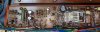
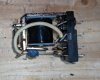
While waiting for my mouser order (it shipped today) I decided to work on the overload protection circuit board. I replaced all of the electrolytic caps as well as the speaker protection relay. The relay had some blackening on the case but I could not see inside to assess it's condition. After I removed it I took the case off and one set of contacts was badly melted from arcing. The amp still worked but I am glad I replaced the relay at this stage. I an guessing whatever took out the right channel output transistors also impacted the relay contacts for that channel. I am attaching a picture of the board after I replaced the components and a closeup of the relay contacts.

PXL_20230206_015007113.jpg

Replaced Components
PXL_20230206_014954086.jpg

Damaged Relay Contact

PXL_20230206_015451202.jpg
 
If it aint broke....... it will break.

This is a 50 year old piece of electronics. Preventative maintenance is needed.
Those transistors with the thin metal tab in the middle of the top of the amp board need to go. KSC3503 and KSA1381.
Be sure to replace those yellow caps with Nichicon KL.
Bourns 3386H should work for the trimmers.

Looks like it needs a bath.

FYI I ordered the Nichicon KL caps 10MF 25V they are end of life so I ordered 25 to have then on-hand going forward. The MY2-02-DC24 relay fit perfectly by the way!

My mouser order arrives tomorrow. In the meantime I re-mounted the pre-amp board so I could confirm that the new relay and protection board caps were working as they should. All worked as it should.
 
My Mouser order has arrived and so I started restoring the phono amp board. I disconnected the output leads to the power amplifiers to allowed better access to the phono board for my restoration work.

Another tool also arrived just before the Mouser order which contained a new solder puller to replace the yellow and blue plastic one I have been using which has seen better days. I was skeptical of all the great reviews that it received but figured for $22 I would give it a try. It has a silicone tube on the end which it was claimed would not be affected by soldering heat. The instructions said to press the rubber tip against the colder connection while heating and then release the plunger. I used it for the first connections I was de-soldering and was amazed at how it worked. I ended up using it for the whole board and the tool really made the process easier. A great little tool that I wish I had purchased earlier. The silicone tube was completely unaffected by the solder heat. ( I have my iron set to 650F).

PXL_20230209_205506314.jpg
 
I replaced all of the transistors on the board as well as all of the electrolytic and several coupling capacitors. I also replaced all of the transistors on the board. the 2SC1400's were replaced with KSC1845 transistors and the 2SA750's were replaced with KSA992 transistors. The 10 UF 25V coupling caps were replaced with low noise modern equivalents as recommended. It took some time but overall the process went smoothly except for one issue I encountered. Capacitor C411 appeared to be installed backwards according to the markings on the Circuit board and in the printed service manual. The dot marks the negative terminal on the electrolytic caps but in the case of C411 it appeared to be incorrect. The cap was original to the unit so I assumed that the board and service document were incorrect in that the amplifier worked. I traced the schematic against the foil on the circuit and confirmed that that was in fact the case, the boar/document were incorrect so I installed the replacement capacitor the same way. I am attaching pictures of the old caps in place and the new ones I installed for reference.

Old capacitors C411 and C412. Notice the black dots indicating the negative lead.

PXL_20230209_213651656.jpg


Replacement Capacitors installed orientated the same way as the original caps.

PXL_20230209_214821923.jpg
 
Here is a picture of the Phono board after I finished replacing all of the components.

PXL_20230211_183150297.jpg

It was a relatively painless process which was a nice surprise for me.
 
Here is a picture of the Phono board after I finished replacing all of the components.

View attachment 2796919

It was a relatively painless process which was a nice surprise for me.
Missed the epoxy diodes, black with yellow dot. Measure the voltage drop, but I believe those are replaced by just one 1N4148.
Missed the tantalum capacitors, the worst offense. Replace with Nichicon KL (low leakage).

You don’t have to bother with the fiberglass sleeves you left on the new Nichicon blue caps.
 
Yep, I did not have the 4.7UF film caps on-hand so I left them alone for now. I will put them on my next Mouser order (seems like I should be on a first-name basis with those folks). I kind of like the fiberglass sleeves so I left them in place, no logical reason.
I am planning on working on the Power amp modules next, figure there will be a few surprises there to add to the mouser order also. Some of the transistors on the power amp board are BCE and their replacements are ECB. (think I have the sequence correct. Fortunately the replacements in question are not heat-sinked so I should be able to just flip them around when I install them.

The power amp modules are pretty stable now, hold bias and DC balance well after warming up. The boards themselves are physically a mess though. I will replace all of the transistors caps etc. and on the right module all the outputs as well.

Will start on it probably tomorrow as it is game day today.
 
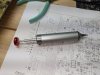
We had company for a week here in Florida so things kind of got sidetracked a bit. I did replace two 220UF caps on the right channel power supply board. They had been replaced previously with 220UF 25V units while the originals were rated at 35V. One of them has a bulging bottom and one connecting lead fell out while removing it. I replaced them both and will go back for the rest of the caps when they arrive tomorrow. I also re-capped the Tone control board and replaced sever 2SA750 transistors on it as they are "shoot on site" transistors so best they go. Here is a picture of the two 220UF 25V caps I replaced.

PXL_20230222_023327401.jpg
 
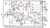
For the last several days I have been working on the Right main (Power) amp on the Rotel. My initial optimism about "just flipping the ECB transistors around" was self-misinformed. It turned out almost all of the replacement transistors were ECB necessitating crossing over the C-B leads to correspond with the board perforations. Fortunately the two existing heat-sinked transistors were ECB which was fortunate. I marked up a schematic indicating by marking the substitute transistor (ECB) indicating the C-B leads needed to be swapped in those cases. I will re-check my work in the morning when I am less bleary-eyed before installing the last capacitor I am waiting for and then re-assembling and testing out my work.

Here is the marked-up schematic. Q604 was mistakenly marked ECB and I crossed it out as you can't edit 2D text in Paint 3D as I found out after the fact.

Rotel  ra-1412 main amp annotated.png
 
For the last several days I have been working on the Right main (Power) amp on the Rotel. My initial optimism about "just flipping the ECB transistors around" was self-misinformed. It turned out almost all of the replacement transistors were ECB necessitating crossing over the C-B leads to correspond with the board perforations. Fortunately the two existing heat-sinked transistors were ECB which was fortunate. I marked up a schematic indicating by marking the substitute transistor (ECB) indicating the C-B leads needed to be swapped in those cases. I will re-check my work in the morning when I am less bleary-eyed before installing the last capacitor I am waiting for and then re-assembling and testing out my work.

Here is the marked-up schematic. Q604 was mistakenly marked ECB and I crossed it out as you can't edit 2D text in Paint 3D as I found out after the fact.

View attachment 2806859
Yeah it's never fun with switching the leads. I always just put some wire insulation over the middle one and bend it. They really should have given multiple options like Sansui!
 
Well I installed the last 470MF 10V capacitor on the Right channel power amp and then re-assembled everything for a test this evening. I hooked up the meter to monitor the bias on the right module so I could check it and dial it in if it was too far out. I hooked up audio input to the AUX1 input, hooked up my testing speakers and plugged the Rotel into the variac. I gradually applied power and at about 60V it came out of protection and was playing beautifully. I started bringing up the AC power normal line voltage and then suddenly there was a crack in the right channel speaker and it went into protection.

I reset everything and started over, now as soon as the Rotel gets to a point it is about to come out of protection there is the same loud crack in the right speaker and then back into protection. I am guessing something in the right power module I just repaired failed. Tomorrow I will remove DC power from the right channel and see if it comes out of protection and plays on the left channel to confirm that the right power amp is the issues. It is interesting but frustrating that it played well for about 30 seconds then "poof". Oh well, tomorrow is another day and I guess I will be disassembling the right power amp to figure out what has failed......
 
I have done some preliminary work on trying to find the cause of the problems with the right channel. I disconnected the power supply from the failing right channel and the Rotel now powers up and comes out of protection and the left channel plays well. I de-coupled the pre and power amps and patched both the left and right pre-amps into the good left channel power amd and both pre-amps played well through the good left channel power amp. I have begun trying to figure out the issue with the right power amp module, so far everything looks correct but I will systematically check everything including by selection of substitute transistors. Maybe I made a mistake somewhere along the way.....
 
Back
Top Bottom