• The move to the new server is done. There are some software and database maintenance updates in process. This has us passing the hat around to help out. We appreciate any donations. Seriously, even a dollar helps. The payment page may be found here - https://www.audiokarma.org/support.html

S-Ruddy's Executive IV Restoration Thread

Steve; According to my sources and my experiences with FISHER consoles and receivers with the bar tube, the EM840 and EM84 are exact subs. You may have a worn out tube.For the EM840 and EM84 use the 6FG6 or the Russian 6e3p. Depending on the wear on the tube, you can have 6 tubes with 6 different bar sizes for the same voltage. No two tubes will show the exact same results. Close, but not exact.

The 6FG6 and 6HU6 can be interchanged but the 6fg6 has less sensitivity than the 6HU6.

From www.magiceyetubes.com
The 6FG6, 6E3p¤, EM84, EM840, and CV5434 are exact substitutes. The 6HU6, EM87, and CV10407 are exact substitutes. The 6FG6 and 6HU6 along with their substitutes may be interchanged, however the 6FG6 has less sensitivity, and requires slightly less filament current.
 
Steve; According to my sources and my experiences with FISHER consoles and receivers with the bar tube, the EM840 and EM84 are exact subs. You may have a worn out tube.For the EM840 and EM84 use the 6FG6 or the Russian 6e3p. Depending on the wear on the tube, you can have 6 tubes with 6 different bar sizes for the same voltage. No two tubes will show the exact same results. Close, but not exact.

The 6FG6 and 6HU6 can be interchanged but the 6fg6 has less sensitivity than the 6HU6.

From www.magiceyetubes.com
The 6FG6, 6E3p¤, EM84, EM840, and CV5434 are exact substitutes. The 6HU6, EM87, and CV10407 are exact substitutes. The 6FG6 and 6HU6 along with their substitutes may be interchanged, however the 6FG6 has less sensitivity, and requires slightly less filament current.

Very good info Larry. Thanks for the link. I wonder why the Fisher service manual lists them as different numbers? They have V12 as EM840 and V11 as EM84/6FG6. Anyway I'll just get another EM84/6FG6. Thanks!
 
I was wondering if I can add a set of external speakers and drive them at the same time as the console speakers?
 
Sure. I have WS-1 Jacks on the back of my '61 Executive. Sometimes I'll plug in a set of 8 ohm speakers like with a live broadcast or recording. I do wish mine had an internal/external/both speaker switch.
 
Yeah. As long as the externals are either 8 or 16 ohm, no problem. They are in parallel so the ohm load on the speakers to the unit will drop, but the circuits can handle it.
 
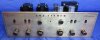
Tuner is finished and sounds great! The Tuner eye tubes were very dim so I purchased two nos tubes from different sources. One is a Valvo the other is Halicraft by amperex. The Valvo is way brighter thean the amperex however the amperex will come within a hairs width of touching on a strong tune. The Valvo leaves about an 1/8th inch. Do I have bad tubes or are they highly variable? Still trying to decide if I should add a MPX unit. Here a few photos. I was playing with different looks. Let me know which one you like the best.

_Z8A5773.jpg


_Z8A6043.jpg


_Z8A6029.jpg
 
I finally found cloth that matches the original rear speaker covers. After searching on the internet for ever I remembered a very old local upholstery business and gave them a visit. The Mom took me back to talk with her son and I showed him a sample. He told me they don't make that material anymore but pulled out a small trash can filled with bits of off cuts of different material. He found two pieces big enough for the job and said take them. Here is a shot showing the restored back next to the faded original. The other was completely ripped up.

_Z8A6601.jpg

Here is a quick shot showing the amp and tuner installed. I still have to finish the wires, the other speaker back and reinstall the back panel. Oh I had mentioned earlier I was having some hum issues but I have traced that down to bad interconnects and a bad 6BQ5 tube. My tube tester passed the shorts, gas and it tested real strong but I could see a very slight red glow to it and it sounded terrible and had intermittent hum. I'm wondering if I had a different model tester if it would have tested for different stuff and shown it was a bad tube. I'm using a Hickok 752. Oh and I have also re constructed the TT drawer and am now rebuilding the original Garrard RC88.

_Z8A6603.jpg
 
Steve; Most all Eyetubes are variable in their responses even at full tilt boogie. I bought a sleeve of 5 nos 6e3p tubes and tested them for open/closed on my EICO 625. All had variance in closure from overlap to about 1/8" open. Even the old valvo, Lorenz, etc brand tubes have variances in response. This is more due I feel to human assy of the internals. I wouldn't worry about it too much as long as the response is consistant with regard to different strength voltages in radio operation.

The 752 does the same tests as my Philco 9100 (which is a Hickok 533a under license from Hickok) but may be a little more accurate, provided that both are calibrated to factory spec's. If it tests all the tubes that you use, keep it. Each tube tester brand and model do the same tests, and that's what they are, just tests. The voltages are a percentage of normal operating voltages and the circuits compensate for the difference. It's a guide, and is to be taken as such, as to the apparent operating condition of the tube, not the actual operating condition. For that you'll need a custom, specialized test rig, usually handmade and very complicated for most.

Commercial testers were made more for TV and radio repairmen going out in the field, and are accurate enough to tell you that the tube will work or it won't work. A long time ago (back in the 70's) I learned that if i considered them to be used for no more than a GO-NOGO piece of gear, I could do the same job and get it done faster. Only in the last 15-20 years have consumers placed more and more importance on "matching" tubes (which none of the commercial units actually do) which places more and more reliance on a piece of test gear that it wasn't designed for. You can find tubes that match emissions and gm, and still have grossly mismatched tubes. Matching tubes means that the tube draw in ma is the same between two or more tubes at an operating voltage that the unit under operation is running. emissions may be close, but gm may be all over the place or close and very very rarely dead on or so close it doesn't matter.

That quad of 6BQ5's may be matched up for your Executive at your plate and screen voltages, but put them in the 481A amp in my 64 Custom Electra and the tube draw will be all over the place due to different operating parameters. Which is why I get all of my output tubes from Jim McShane and make note to him of the plate voltage, screen voltage, whether fixed or cathode bias, and the make/model of the unit in question. Then when I get the tubes they are marked for that unit and stay with/in that unit. Any extra quads I get, I go thru the same procedure and I get tubes with the same load conditions as the original tubes or as close as Jim can get (+/- 2ma).

So go ahead and use the 752 knowing that it's working the best it can for what it was designed to do. Compare each tube against itself, which is what it's really good at, not against other tubes.
 
I agree with Larry. Your one 6BQ5 may be perfectly good, but not sufficiently matched to the other three to work properly in your X-101. That unit does work the output tubes fairly hard, as they need to pull enough current to light the phono preamp tube heaters. If they are not balanced sufficiently at the operating point, then which ever poor tube requires more bias voltage to operate at a given quiescent current point gets nailed.

Your project is turning out simply gorgeous!

Dave
 
Steve; Most all Eyetubes are variable in their responses even at full tilt boogie. I bought a sleeve of 5 nos 6e3p tubes and tested them for open/closed on my EICO 625. All had variance in closure from overlap to about 1/8" open. Even the old valvo, Lorenz, etc brand tubes have variances in response. This is more due I feel to human assy of the internals. I wouldn't worry about it too much as long as the response is consistant with regard to different strength voltages in radio operation.

Ahh great to know Larry. I went with the Halicraft Labeled Amperex. It closes to about 1/32" which is much better than the 1/8th I was getting from the Valvo. I may put the Valvo in the am socket since it probably won't be used much if at all.

You can find tubes that match emissions and gm, and still have grossly mismatched tubes. Matching tubes means that the tube draw in ma is the same between two or more tubes at an operating voltage that the unit under operation is running. emissions may be close, but gm may be all over the place or close and very very rarely dead on or so close it doesn't matter.

Here is were I get confused. What's the difference between emmisions and gm? I think my tester only tests for the latter.

That quad of 6BQ5's may be matched up for your Executive at your plate and screen voltages, but put them in the 481A amp in my 64 Custom Electra and the tube draw will be all over the place due to different operating parameters. Which is why I get all of my output tubes from Jim McShane and make note to him of the plate voltage, screen voltage, whether fixed or cathode bias, and the make/model of the unit in question. Then when I get the tubes they are marked for that unit and stay with/in that unit. Any extra quads I get, I go thru the same procedure and I get tubes with the same load conditions as the original tubes or as close as Jim can get (+/- 2ma).

Nice I like and use Jim as well. I haven't purchsed tubes from him yet. So far I use the auction site and Brent Jesse when I want matching and curve tracing. He usually marks the boxes with ma which I assume is light gm? I have also seen plate current and plate volts. I have no idea how these figure relate to the circuit I'm using them in. I need to visit the tube forum and get a better understanding of tubes and the applications.

So go ahead and use the 752 knowing that it's working the best it can for what it was designed to do. Compare each tube against itself, which is what it's really good at, not against other tubes.

Probably having a lame brain moment again but what do you mean by comparing a tube to itself?

I agree with Larry. Your one 6BQ5 may be perfectly good, but not sufficiently matched to the other three to work properly in your X-101. That unit does work the output tubes fairly hard, as they need to pull enough current to light the phono preamp tube heaters. If they are not balanced sufficiently at the operating point, then which ever poor tube requires more bias voltage to operate at a given quiescent current point gets nailed.

Your project is turning out simply gorgeous!

Dave

Thanks Dave!

Here are some numbers and info. Let me know if you think my current tubes are in the right place.

Mullard (currently in place)
  1. V-10 / 850gm
  2. V-9 / 675gm
  3. V-5 / 800gm
  4. V-4 / 550gm

When I had the GE tubes in the 750gm tube is the one showing a slight red glow seen when room light s were out so I am just guessing that it the tube causing hum and bad audio.

GE ( #1 slight red, terrible sound with these tubes)
  1. V-10 / 750gm
  2. V-9 / 800gm
  3. V-5 / 575gm
  4. V-4 / 825gm
 
Last edited:
S -- The reason that you're getting confused is because output tubes that are properly matched are matched based on two aspects of their performance: That under DC or static conditions, and that under AC or dynamic conditions.

Dynamic testing is performed by applying an AC drive signal to the tube and then measuring it's current output. When the drive signal is very small, the result is a measurement of transconductance or Gm, which is an indication of the tube's ability to amplify. Such tests are performed at rather low operating voltages, and so do not test a tube under truly real world operating conditions, but it still is quite useful to show that a tube is capable of its basic function. Power output tubes should ideally be measured using a large drive signal, giving the ability to measure the tube's power output -- which is much more meaningful based on what the tube is designed, and supposed to do. But equipment that can measure the latter parameter under real world conditions is necessarily more complex and bulky, so that virtually ALL of the better commercial testers measure a tube's ability to amplify in terms of small signal Gm. This is the type of test results you have shown for your tubes.

Static testing does not apply any kind of drive signal, but simply applies operating voltages, and then the grid bias voltage required to produce a given current draw is recorded (or visa-versa). It is this characteristic that will cause a tube to show color if not well matched to its mates, as it is the static matching that determines how well a set of tubes are balanced under quiescent (no signal) conditions in your amplifier/receiver. It is this data that is missing from the results you have posted, so that while (your) tubes can be well matched under dynamic conditions, they can still be quite mismatched under static conditions.

The best tubes sets then are matched for both static and dynamic characteristics, so that when installed in your unit, not only will the tubes be matched in current draw under quiescent conditions (so that they will all share equally in the total current drawn), but also will amplify equally under dynamic (signal) conditions, allowing for the most power and the least amount of distortion to be produced.

I hope this helps!

Dave
 
Last edited:
How did you get the brass faceplate so shiny and clean? I'd love to get my early X-100 lookin' like that!View attachment 737072

Hi Beatcomber,

My faceplates were top coated with lacquer at the factory. I'm assuming yours was too, but don't know how it got to how it looks now.The only two things that had happend to the lacquer coating on my faceplates is yellowing and light scratches. So I treated it like it's a car finish and used a 3M Micro fine and Ultra fine polishes. I think I may have posted a photo of them earlier. That took any light surface scuffs and scratches away and left the lacquer with a nice even shine. Of coarse any yellowing is still there, but since the color is gold it probably doesn't look to much different than new. So if the discoloration and mottling on your unit are on top of the lacquer your should be in luck! Nice knobs BTW!! Those babies are getting ridiculously expensive.

Steve
 
S -- The reason that you're getting confused is because output tubes that are properly matched are matched based on two aspects of their performance: That under DC or static conditions, and that under AC or dynamic conditions.

Dynamic testing is performed by applying an AC drive signal to the tube and then measuring it's current output. When the drive signal is very small, the result is a measurement of transconductance or Gm, which is an indication of the tube's ability to amplify. Such tests are performed at rather low operating voltages, and so do not test a tube under truly real world operating conditions, but it still is quite useful to show that a tube is capable of its basic function. Power output tubes should ideally be measured using a large drive signal, giving the ability to measure the tube's power output -- which is much more meaningful based on what the tube is designed, and supposed to do. But equipment that can measure the latter parameter under real world conditions is necessarily more complex and bulky, so that virtually ALL of the better commercial testers measure a tube's ability to amplify in terms of small signal Gm. This is the type of test results you have shown for your tubes.

Static testing does not apply any kind of drive signal, but simply applies operating voltages, and then the grid bias voltage required to produce a given current draw is recorded (or visa-versa). It is this characteristic that will cause a tube to show color if not well matched to its mates, as it is the static matching that determines how well a set of tubes are balanced under quiescent (no signal) conditions in your amplifier/receiver. It is this data that is missing from the results you have posted, so that while (your) tubes can be well matched under dynamic conditions, they can still be quite mismatched under static conditions.

The best tubes sets then are matched for both static and dynamic characteristics, so that when installed in your unit, not only will the tubes be matched in current draw under quiescent conditions (so that they will all share equally in the total current drawn), but also will amplify equally under dynamic (signal) conditions, allowing for the most power and the least amount of distortion to be produced.

I hope this helps!

Dave

Thanks Dave, I had to read the Wiki to understand everything you mentioned but I think I got it! So I assume I really should have an emissions tester, as well as my mutual conductance tester, if I want to match output tubes without having a tester with a large drive signal. I suppose a curve tracer does this? In the meantime I'm guessing all I can do is use the closest gm readings per channel pairs. Does this mean a channel with the tubes having lower gm readings have less output ability?
 
S -- I don't mean anything by it, but don't waste your money on an emission tester. Again, they test a tube at such low voltage and current scenarios as to be of little help in determining how a given pair of tubes will pair up in real world conditions.

You would do far, FAR better to simply add 10 Ohm current sensing resistors to your existing amplifier, and then measure the current draw of all your various tubes IN THE AMPLIFIER under quiescent conditions. Then use those that line up for the closest, balanced current draw -- and check to see their Gm is reasonably balanced in your current tube tester. That process will let you pair up the most balanced sets out of all your tubes, and spend just a buck or two on a few resistors.

Dave
 
S -- I don't mean anything by it, but don't waste your money on an emission tester. Again, they test a tube at such low voltage and current scenarios as to be of little help in determining how a given pair of tubes will pair up in real world conditions.

You would do far, FAR better to simply add 10 Ohm current sensing resistors to your existing amplifier, and then measure the current draw of all your various tubes IN THE AMPLIFIER under quiescent conditions. Then use those that line up for the closest, balanced current draw -- and check to see their Gm is reasonably balanced in your current tube tester. That process will let you pair up the most balanced sets out of all your tubes, and spend just a buck or two on a few resistors.

Dave

Ok will do, you all told me how to do that on my x-202b and it definitely makes much more sense. Thanks for reminding me, I thought a fixed bias amp wouldn't need that mod but didn't think of using it to balance tubes!
 
Hi Beatcomber,

My faceplates were top coated with lacquer at the factory. I'm assuming yours was too, but don't know how it got to how it looks now.The only two things that had happend to the lacquer coating on my faceplates is yellowing and light scratches. So I treated it like it's a car finish and used a 3M Micro fine and Ultra fine polishes. I think I may have posted a photo of them earlier. That took any light surface scuffs and scratches away and left the lacquer with a nice even shine. Of coarse any yellowing is still there, but since the color is gold it probably doesn't look to much different than new. So if the discoloration and mottling on your unit are on top of the lacquer your should be in luck!

Many thanks for that info! The AK'er that I purchased it from had carefully used Brasso to remove much of the tarnish from the faceplate, so I'm not sure if any of the lacquer remains or not. I'd like to clean up the remaining mottling, but I'd be devastated if the printing were wiped away in the process. What to do, what to do...?

Nice knobs BTW!! Those babies are getting ridiculously expensive.

Thanks! The previous owner said that it took him the better part of a year to find a few needed replacements on eBay!
 
S -- Just remember that in your 202B, the output tube cathodes (basically) operate at ground potential by design -- where as in your X-101, they DO NOT. It is still perfectly practical to install the individual cathode current sensing resistors in your X-101, but rather than installing them between the cathode terminal and ground (as in your 202B), you will install them between the cathode terminal and the wiring that is currently attached to it. If you install test points to make for easy checking and adjustment, then you will actually install 5 such terminals (4 red, 1 black), with the red terminals being tied to the cathode terminal of the four tubes, while the black terminal is tied to the cathode "buss" wiring -- which is the daisy chain wiring running between the cathode terminals in the original design. In this way then, to check a specific tube, you would connect your meter's black lead to to the black test point, and your red lead to the red test point of the tube in question.

Good luck with it!

Dave
 
S -- Just remember that in your 202B, the output tube cathodes (basically) operate at ground potential by design -- where as in your X-101, they DO NOT. It is still perfectly practical to install the individual cathode current sensing resistors in your X-101, but rather than installing them between the cathode terminal and ground (as in your 202B), you will install them between the cathode terminal and the wiring that is currently attached to it. If you install test points to make for easy checking and adjustment, then you will actually install 5 such terminals (4 red, 1 black), with the red terminals being tied to the cathode terminal of the four tubes, while the black terminal is tied to the cathode "buss" wiring -- which is the daisy chain wiring running between the cathode terminals in the original design. In this way then, to check a specific tube, you would connect your meter's black lead to to the black test point, and your red lead to the red test point of the tube in question.

Good luck with it!

Dave

Ha Ha, your getting to know me Dave, I like how you have anticipated my next question.

I was listening to the radio last night while restoring the TT and all of the sudden the amp started buzzing loud! Scared the crap out of me. I turned the tuner off but it didn't go away. Then I the turned the amp off and on and it went away. Ten minutes later it came back. This time I changed stations and it went away for the rest of the evening. I have no idea what's going bad so I guess I'll check all the voltages again and test all the resistors which I didn't do the first time around. I'm also considering doing the cap change for the bass output but the reason I'm just considering it is that I seem to have plenty bass. The only time I can use the loudness switch is if the volume is very very low. Normally I run the treble centered and the bass at +1.5 so I'm wondering if changing the caps will result in too much bass and muddy sound.
 
If anything changing the caps will give you a more detailed bass, without increasing the bass. The loudness switch is designed for the exact conditions you are using it for. There is a curve that describes how you hearing perceives frequencies at certain volumes. These are known as Fletcher-Munson curves. Here's some light reading. https://www.google.com/url?url=http...ggUMAA&usg=AFQjCNGlm2IhF7vN8EiFAY0fq3VenUv_aA

Basically at low volumes bass and treble appear to be attenuated more than mid range frequencies. So the bass and treble frequencies get boosted either by application of the Bass and treble controls, or the loudnes control or for the more extreme guys, Both. As volume increases, Bass and treble boost is attenuated down to normal levels, with the loudness eventudally being non functional somewhere near 1/2 volume (by knob position).
 
Back
Top Bottom