• The move to the new server is done. There are some software and database maintenance updates in process. This has us passing the hat around to help out. We appreciate any donations. Seriously, even a dollar helps. The payment page may be found here - https://www.audiokarma.org/support.html

Sansui 1000X Tuner trouble

I decided to try setting the IF first. Used a 10 pF cap on the input 10.7 MHz signal and a 0.01 µF cap on the output. There are three adjustments for IF, T201, 202, and 203 both primary and secondary coils. I did get response on all of them and adjusted for maximum signal.

Also set discriminator on T204, again set for max signal.

Did not notice much change in pulling in stations. I can get the stronger ones in the area clearly, but the signal meter does not move, and no stereo. So, really no improvement over before. The stations are coming in dead on with the dial, so all indications seem to be the alignment went ok.

I bought this from a local person who buys/sells/"fixes" vintage gear. It was apparent it was having trouble pulling in stations when I bought it, and we agreed I could take it back for a refund if I an alignment did not solve the problem (he doesn't align tuners), so I think this will be going back. Otherwise it is a nice receiver. Listened to a CD on Aux and the sound is very good - very much what one would expect from a vintage Sansui, but I can't really invest a lot of time in it for the price I paid (which assumed it was working.) Possibly there is a bad transistor or cap on the FM board?
 
A few more thoughts...

After sleeping on this one, I'm not sure I should give up on this tuner just yet? It just seems odd that there is response to all of the adjustments I was making (in the right direction), but still low signal on an antenna. I did discover that in the past I was using around 60 dbf for signal amplitude setting the dial frequencies rather than 60mV! :eek: It's been a while since I last did an alignment, so I had forgotten the units. Would it make a difference if I went back and did the dial adjustments at the lower amplitude? Right now the stations are coming in pretty much right where they should on the dial, but that might not be the only indication things are adjusted right?
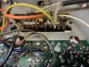
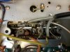
I can try to find the points Ylli indicated to do a test on the FET. Not sure anything is labeled in there, so it will take some in investigating.

I'd still like to get my HP 8657A and 8904 to generate a sweep signal. I did try setting the 8904 for a saw tooth modulation into the 8657A, but didn't see a sweep signal. However, I have no idea if I had the settings right on the 8904 or the oscilloscope. May try messing around with that again. I noticed i could maximize the 10.7 MHz signal into the scope, but there was often some "range" over which the signal stayed the same at a max voltage value. So, maybe this is where the shape of the signal is changing?

Here is the thread where others shared their approach to setting the IF and discriminator not using a sweep signal. That part of the discussion is on page 4 starting at post #80 https://audiokarma.org/forums/index.php?threads/sansui-tu-9900-no-fm-stereo.894134/page-4
 
Right now the stations are coming in pretty much right where they should on the dial, but that might not be the only indication things are adjusted right?
That only indicates the Local Oscillator is properly adjusted to track the dial indications.

can try to find the points Ylli indicated to do a test on the FET. Not sure anything is labeled in there, so it will take some in investigating.
If you can see all the sections of the variable cap, point 4 would be the section closest to the antenna input. The section next to it would be point 2. The section furthest from the antenna input would be the local oscillator.

I noticed i could maximize the 10.7 MHz signal into the scope, but there was often some "range" over which the signal stayed the same at a max voltage value.
May indicate that you are overdriving it and the IF is in limiting, or it might be an indication that the IF transformers are overcoupled and the IF really needs to be swept for a proper tuning. Reduce the signal level until the peak is well defined.
 
That only indicates the Local Oscillator is properly adjusted to track the dial indications.

If you can see all the sections of the variable cap, point 4 would be the section closest to the antenna input. The section next to it would be point 2. The section furthest from the antenna input would be the local oscillator.

May indicate that you are overdriving it and the IF is in limiting, or it might be an indication that the IF transformers are overcoupled and the IF really needs to be swept for a proper tuning. Reduce the signal level until the peak is well defined.
Great, thanks for those tips. I will see if I can locate the correct points on the variable cap tonight and give that a try.

I was using 200 µV amplitude when setting the IF and discriminator. I can dial that down and go through the procedure again. The signal did not look clipped or odd shaped - just a regular sine wave.

I will probably fiddle with the 8904 to see if I can get it to create a sweep signal with the 8657A if the previous steps don't show any promise.
 
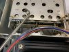
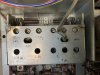
I took a close look at the underside of the variable cap. Lots of evidence that someone has been in here before working on this area. The two screws that hold the housing in place are missing. Several posts have marker on them. On top some sloppy solder jobs. I wrote the numbers on the top by each adjustment point.

In either case, @Ylli can you see where I should be making connections? Sorry to ask so often, but just don’t want to mess something up. Wondering if whoever took the screws out did some permanent damage in there?

0C2DF4C4-AF8B-4C1F-A436-6E342A44611E.jpeg FA68F8C9-4B29-4408-80B0-D43C355B23D5.jpeg D2499F2D-3CB6-44FD-8320-E53BB68B1820.jpeg EFB5CE2B-8EF0-4E95-ADD2-E61E282886F4.jpeg 3686BC50-3605-4C68-A5DF-1D2B1FC3120E.jpeg
 
Well, went through the O.S.C and RF amp circuit procedure again but with much lower signal amplitude (100 - 300 µV), and here is the result:

CA97EF4A-8F95-4B4C-B4DF-F8F875408EE3_1_201_a.jpeg

Getting decent signal reception. Not as good as some of my other receivers, but fairly average. Will probably go back and check IF and discriminator with as low an amplitude as I can get away with to get better response in the adjustments, then go back through the OSC and RF amp again. Will report back how it goes. So far so good. :beerchug:
 
The part of the variable capacitor that does not move when you tune the receiver. Point 4 at the far right, point 2 the next (smaller section) cap to the left. [the larger sections are for tuning AM]
Annotation 2020-08-05 223759.jpg
 
The part of the variable capacitor that does not move when you tune the receiver. Point 4 at the far right, point 2 the next (smaller section) cap to the left. [the larger sections are for tuning AM]
View attachment 1945922
OK, put a signal in at point 2 and adjusted amplitude to hear the signal. Also had tape out connected to the scope. I was getting about 2.5 amplitude on the scope. Input signal at point 4, and it was clearly amplified in the headphones, and scope was reading about 8.3.
 
Well, sounds like the FET is amplifying. I would have expected a larger change though. Don't think I have any further suggestions.
 
Well, sounds like the FET is amplifying. I would have expected a larger change though. Don't think I have any further suggestions.
Interesting, thanks for that information. Is there a replacement for that FET that you know of if I want to give that a try?

My plan next is to go through the IF and discriminator alignment again with a lower signal to optimize those, and back again through the OSC and RF amp, then adjust stereo separation, and see what that gets me. I guess I'm not expecting a fantastic tuner, just want to optimize it as best I can. Again, this receiver has a really nice sound to it.
 
Everything I can find that comes close seems to be obsolete. Might want to post a new thread looking for a replacement for it (2SK19). You'll get more eyes on it that way.
 
You can always try Littlediode.. seem to have them in stock, but no price listed. Wouldn't be cheap.
 
Any idea how much improvement I would see with a new FET in there? In other words, would it be worth it?
 
Been my experience, not much. Either work or don't, Ensure your bias voltage are correct.
 
Been my experience, not much. Either work or don't, Ensure your bias voltage are correct.
Thanks, Mike. Just set the bias today. It was pretty close. The tuner is working ok. I’m sure it’s no surprise this lower end receiver doesn’t have the best turner. Great sound for the stations it does get. Just picked up a 5000X, THAT tuner is very impressive.
 
Interesting, thanks for that information. Is there a replacement for that FET that you know of if I want to give that a try?

My plan next is to go through the IF and discriminator alignment again with a lower signal to optimize those, and back again through the OSC and RF amp, then adjust stereo separation, and see what that gets me. I guess I'm not expecting a fantastic tuner, just want to optimize it as best I can. Again, this receiver has a really nice sound to it.
I've bought parts from this supplier before. They seemed to be legit:
https://www.rfparts.com/catalogsearch/result/?q=2sk19
 
Well, went through the O.S.C and RF amp circuit procedure again but with much lower signal amplitude (100 - 300 µV), and here is the result:

Here's my experience for a problem like this - you should get an "almost" clean audio tone out of the tuner from a 100% modulation mono (pilot off) RF test signal with a 2-3 uV RF test signal. It should be very clean at 5uV. If this is not so, and way off, (i.e. noisy at 10-15 uV level) you have a problem in alignment, RF amp, or IF amps. I have seen bad IF amps, too. This is true for every tuner I have ever worked on. Some are better and go to noise below 1uV.
I have not noticed in previous messages, but make sure you clean the tuning gangs, sometimes it takes 2-3 passes on the procedure for really dirty ones.
Bob
 
Here's my experience for a problem like this - you should get an "almost" clean audio tone out of the tuner from a 100% modulation mono (pilot off) RF test signal with a 2-3 uV RF test signal. It should be very clean at 5uV. If this is not so, and way off, (i.e. noisy at 10-15 uV level) you have a problem in alignment, RF amp, or IF amps. I have seen bad IF amps, too. This is true for every tuner I have ever worked on. Some are better and go to noise below 1uV.
I have not noticed in previous messages, but make sure you clean the tuning gangs, sometimes it takes 2-3 passes on the procedure for really dirty ones.
Bob
What is the procedure you use for cleaning the tuning gangs?
 
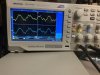
Put a 104 MHz signal (quiet spot on the dial) in to the antenna terminals, 1000 Hz 100% modulation. Took tape out signal to the scope. Here is the signal at 3 µV input amplitude.

9192C832-28B8-4AD1-8573-3296E18B3DF7.jpeg

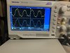
Here is the signal at 5 µV amplitude.
126BDC56-74B0-4267-AD97-D37852F9237C.jpeg

Last, signal at 10 µV amplitude.
8AA69783-3783-4689-A093-B37FC464A074.jpeg
 
Back
Top Bottom