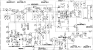
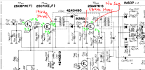
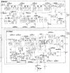
I don't get it either . . . probably my lack of info and understanding. Here are some more measurements for TR403 to help:
........................................B....................C..................E
No Sig..........................13.1...............0..................7.47
40dBu no pilot..........13.37............0..................7.43
40dBu w/pilot............13.84...........1.54.............14.5
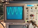
So it appears that TR403 is being turned on as the signal w/pilot is increased. At 40dBu input (75% modulation, 7.5 kHz, EDIT - was % - pilot) i get a solid 38 kHz output from the collector of TR403. As i decrease the input signal, I lose the 38 kHz signal at the collector of TR403 around 26 dBu.
So I think the 19 kHz signal from TR401 collector feeds the circuit below (TR409, D407/D408, TR410/TR419 etc.) to switch the MPX on and off. When it's on, TR413 allows TR403 to conduct. The point it turns on at should be adjustable by VR402 and muting should be adjustable by VR403, but neither of those seem to have much effect.
4B input to MPX board/2D output from the IF board is 2.47VDC at 40 dBu input and 1.84VDC at 26 dBu input.
TR205 base has 80 mV P-P 10.7MHz signal and TR205 collector has 2.3V P-P. TR206 base has 0.57V P-P and TR206 collecotr has 7V P-P . . . seem reasonable?
Thanks for your continued help . . . I'm starting to understand IF & MPX, but it's a slow process.