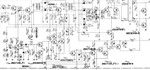
Correct.TR413 off, not on, allows TR403 to conduct, yes?


Correct.TR413 off, not on, allows TR403 to conduct, yes?


That is not what they do. They rectify the ultrasonic noise present above the MPX information. If the signal is noisy they produce voltage and eventually switch on TR413 killing the stereo. This is a signal quality based mono/muting switchover, not signal level based. Yamaha even does that for the signal indicator. The less noise, the better the signal and the higher the indication (more LEDs in that case, T-505 if I recall correctly). So your not getting any 19 kHz on the diodes is how it should be.The diodes rectify the 19Khz pilot to a DC level turning TR409 on or off depending on the level of the pilot received. To control mono/stereo and muting on/off down the line.

That is not what they do. They rectify the ultrasonic noise present above the MPX information. If the signal is noisy they produce voltage and eventually switch on TR413 killing the stereo. This is a signal quality based mono/muting switchover, not signal level based. Yamaha even does that for the signal indicator. The less noise, the better the signal and the higher the indication (more LEDs in that case, T-505 if I recall correctly). So your not getting any 19 kHz on the diodes is how it should be.
You have to calculate the frequency for the notch filter C418/L402. Filling in these values in an online calculator (like this one) results in 73 kHz. Combined with the small value of C417 it looks like this results in a response that starts way above the MPX spectrum. I would have to simulate the circuit to be sure. In any case, replacing transistors willy-nilly is not going to solve your issue. I mean, the circuit works but apparently refuses to adjust. This is odd behavior and out of the blue I cannot say what could cause this. If your stereo generator has an adjustable output (looks like it does) this is easy to measure. Just turn down the level and see when TR410 starts to conduct. It is in parallel with TR419 and that is bad engineering because it could cause one transistor to siphon base current away from the other preventing it to go into conduction. If you are hell bent on replacing transistors that would be a good place to start. If you do make sure the replacements have an identical V(be). As for bad engineering, the whole circuit is a bit... funny.Very interesting. That explains the odd looking wave forms I get around that circuit and the decreasing output with increased signal input. Does the 4.7 mH inductor shunt the 400 Hz / 19 kHz signal to ground allowing only the high frequency noise to reach the base of TR409?

I hadn't thought of the IBOC mess now present in the US. Use your scope before attempting to modify the circuit in order to learn how it behaves with the noise of it present. Compare with your signal generator. Maybe you will have to revert to signal level only muting/stereo switchover. For that, just remove R444 and use VR402 (stereo/mono switchover) and VR403 (muting). Easy peasy.There are a lot of secondary (IBOC) signals being transmitted in this range these days that would not have existed when the circuit was designed. Maybe you should disable the circuit and see what performance you get without it?