• The move to the new server is done. There are some software and database maintenance updates in process. This has us passing the hat around to help out. We appreciate any donations. Seriously, even a dollar helps. The payment page may be found here - https://www.audiokarma.org/support.html

Sansui 8080DB Restoration

BradWil

AK Subscriber
Subscriber
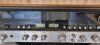
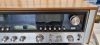
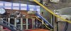
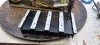
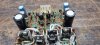
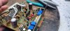
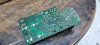
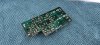
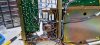
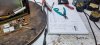
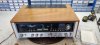
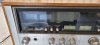
This multi-voltage, penultimate Dolby receiver came across my bench recently for a full restoration. Physically, the unit was complete with no missing knobs or switch covers. It even has the original plastic Dolby switch tag and red cardboard phono advice on the rear. It passed DBT and powered on with full voltage (240V) but stuck in protection.
20220401_101544.jpg 20220401_101548.jpg 20220401_101550.jpg 20220401_101552.jpg

Under the hood

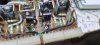
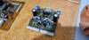
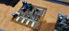
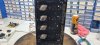
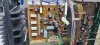
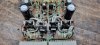
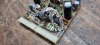
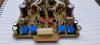
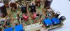
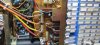
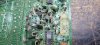
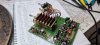
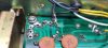
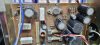
The unit has only a minimal number of caps replaced with the PS and driver amp having all original caps, including filter caps. All transistors appear to be original, bar an odd pair of PNP drivers. The infamous fusible resistors are present with faded colour codes barely visible. Tuner PS board looks a little toasty. Poor solder work to PS tracks evident and burnt earth rail replaced with insulated tinned wire (not shown in photo). Original Sanken outputs 2SA747 & 2SC1116 installed. Thermal paste dry and well past its use by date and likely factory original. Preamp/EQ board very grimy with some questionable caps present.
20220401_190934.jpg 20220401_191619.jpg 20220401_191623.jpg 20220401_194717.jpg 20220401_194954.jpg20220410_132226.jpg
 
Last edited:
Register to hide this ad
PS and F-2624 Driver Amp

Due to the amount of grime and flux, I decided to remove the PS and clean both with RS Safewash 2000, rinse and dry. I have a habit of removing the trimmers and recording their values prior to washing, as they will be replaced with Bourns multi-turn. Faceplate and heatskink cleaned too.

20220401_200637.jpg 20220401_200645.jpg 20220401_200646.jpg

Outputs all tested fine so have been retained and mounted with quality SilPads. Thermal paste to heatsink/chassis mating surfaces.

20220402_153235.jpg 20220402_153936.jpg

Power Supply

The prolematic BP caps near the Molex driver amp connection were replaced with 4.7uF 100V Nichicon UVP series. The rest replaced with Nichicon PW.

R31, R32, R33 toasted fusistors repalced with 1Ω 1W mounted with ceramic spacers. R32 was open and R31/33 measured in the kiloohms.

UPDATE: https://audiokarma.org/forums/index...080db-restoration.998075/page-2#post-15665330

TR01 2SD438 > KSC2690
TR02 2SB560 > KSA1220
TR03 2SD315 TO66 > MJE15032 TO220
TR04 2SC1211 > KSC2383
ZD01 EQA01-13R > 1N5243B

Pin 15 stable at 47.8V
Pin 18 stable at 55.2V

This appears to be close to what others have mentioned, as I understand the schematic is incorrect.

20220523_084834.jpg
 
Last edited:
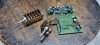
F-2624 Driver Amp

I’ll admit, I struggled with this board. I was able to get DC and bias set and the amp out of protection but no sound, even when feeding a signal into the Main-In directly. As you’ll read later, it may haven been down to those troublesome flat green ribbon cables that run from the main/pre links to the preamp board.

Parts were replaced on the original F-2624 as follows:

All fusistors replaced
C01, C02 Nichicon FG:
C05, C06 Panasonic FM
C07, C08 Nichicon PW
C09, C10 Panasonic FM
D01-D04 1S2473 > 1N4148 400mA
D05, D06 VD1212 > 2 x 1N4148 400mA in series
D07, D08 (silk screened in reverse) 1S2473 > 1N4148 400mA
D09-D16 1S2473 > 1N4148 400mA
ZD01, ZD02 EQA01-24R > 1N4749
TR01-04 2SC1400 > ZTX694B gain matched
TR05, TR06 2SA899 > KSA1220
TR07, TR08 2SC1904 > KSC2690
TR11, TR12 2SD381 > MJE15032
TR13, TR14 2SB536 > MJE15033
TR15, TR16 2SC945 > KSC1845
TR17, TR18 2SA733 > KSA733
VR01-04 Replaced with multi-turn Bourns

20220402_161525.jpg 20220402_161528.jpg 20220402_161608.jpg 20220402_200317.jpg 20220402_200350.jpg 20220403_161207.jpg 20220403_161214.jpg 20220403_161300.jpg

In the end, I came across the Tolitoms re-engineered F-2624 PCB and you can see the successful use of this board in this separate post https://audiokarma.org/forums/index...pcb-build-sansui-8080db.997069/#post-15655114
 
Last edited:
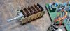
F-2657 Protection Board

To gain better access to the lower tone, switch, protection and Dolby modules, the entire front end of the amp including gang and dial string is easily removed. No need to risk restringing.
Thank you, Sansui engineers!

The protection board was pretty grubby on inspection with evidence of past creature inhabitants. For unknown reasons, previous repairer had removed the Molex plug and input leads were soldered directly to the male pins – strange but secure. Once again, the board was removed to restore it properly. Trimmers and relay removed then the board cleaned and dried.

R12 was toast and was replaced with 1.5KΩ 2W metal film.

R25, R26 fusistors also heat stressed and replaced with 4.7Ω 5W a tad overkill but managed to fit.

TR1-TR4 2SC945/2SC711 > KSC945 closely gain matched around 270 hFE

Electrolytics replaced with Nichicon FG, PW, WIMA MKS2 and Panasonic FM.

Mylar caps replaced with Panasonic ECQE polyester.

Relay contacts cleaned & relay and trimmers reinstalled with original values.

20220401_104022.jpg 20220403_192317.jpg 20220403_200644.jpg 20220403_202058.jpg 20220403_202111.jpg 20220403_202114.jpg 20220403_202644.jpg 20220403_202648.jpg 20220404_194410.jpg20220404_102823.jpg
 
Last edited:
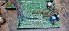
Good catch on changing the SD315 T0-66 to the MJE15032, I will 'ahem' borrow your idea of fully removing the power supply board next time instead of rebuilding it in place just as I now do with the AU517/717 to remove all the nasty glue. Ditto the bp cap upgrade to the 4.7uf 100v Nichicon. Did you get the parts for the sub power supply upgrade?
 
F-2654 Push Switch Board

Once again, the Molex plugs have been removed and the shielded leads from the F-2653 EQ have been soldered directly to the male pins. Perhaps it was to address a known weak point but likely done whilst troubleshooting the infamous green flat cable issues by a previous tech.

In this case the green cables were limited to the EQ board and sturdier black solid core ribbon was used to connect the F-2654 to the F-2655 Dolby board. Unsoldered from the Dolby board and left the switch board in situ.

Only C07 was changed on this board for Elna RFS

Deoxit into the push switches working in and out to clean, while they were more accessible.

20220404_194502.jpg 20220407_175503.jpg
 
F-2655 Dolby NR Board

Much has been written about this board on AK so I’m not going to reinvent the wheel here.

First job was to remove the board from the unit then:

Removed the wafer rotary switch mechanism being extremely careful not to break off the few legs that were bent to hold the switch in place.
Remove the trimmers, measuring their values so they can be replaced as they were.
I left the Dolby pots in situ attached to F-2694.
I chose to carefully record polarity and remove all electrolytic and tantalum caps, as it allows for better access to the pass throughs. Silk screen cap polarity was 100% correct on this unit.
Cleaned the entire board with RS Safewash 2000, dried and cleaned and lubricated the Dolby pots.

Spent the next few hours repining the 60 or 70 pass throughs using previously saved capacitor legs.
A very fiddly job but IMO necessary to ensure longevity of this receiver. If the pass throughs have not failed now, they will eventually so whilst the board is out, you may as well do it.
Double and triple checked every pin and tested with a DMM.

All caps replaced with Elna RFS, apart from the 1uF caps which were replaced by WIMA MKS2.

The switch assembly was carefully cleaned both sides of the wafers, lubricated and reinstalled to the PCB.

20220407_180553.jpg 20220407_180557.jpg 20220407_180600.jpg 20220407_180602.jpg 20220407_180631.jpg 20220407_194433.jpg 20220407_194510.jpg 20220407_195100.jpg 20220410_091539.jpg 20220410_091915.jpg
 
Last edited:
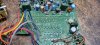
Another board that would be a hit from a modern ToliTom creative effort --- or capable others of course however the ToliTom designation is becoming legendary amongst the Sansui tech crowd likewise RC in the Pioneer forum.
 
Another board that would be a hit from a modern ToliTom creative effort --- or capable others of course however the ToliTom designation is becoming legendary amongst the Sansui tech crowd likewise RC in the Pioneer forum.
I'd like to try and recreate a vintage PCB but I'm not starting with this ;) I may try to create an Eight Deluxe protection PCB clone for use in standard Eights to replace the crowbar cct
 
Last edited:
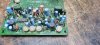
PS and F-2624 Driver Amp

Due to the amount of grime and flux, I decided to remove the PS and clean both with RS Safewash 2000, rinse and dry. I have a habit of removing the trimmers and recording their values prior to washing, as they will be replaced with Bourns multi-turn. Faceplate and heatskink cleaned too.

View attachment 2580508 View attachment 2580509 View attachment 2580510

Outputs all tested fine so have been retained and mounted with quality SilPads. Thermal paste to heatsink/chassis mating surfaces.

View attachment 2580511 View attachment 2580512

Power Supply

The prolematic BP caps near the Molex driver amp connection were replaced with 4.7uF 100V Nichicon UVP series. The rest replaced with Nichicon PW.

R31, R32, R33 toasted fusistors repalced with 1Ω 1W mounted with ceramic spacers. R32 was open and R31/33 measured in the kiloohms.

TR01 2SD438 > KSC2690
TR02 2SB560 > KSA1220
TR03 2SD315 TO66 > MJE15032 TO220
TR04 2SC1211 > KSC2383
ZD01 EQA01-13R > 1N5243B

Pin 15 stable at 47.8V
Pin 18 stable at 55.2V

This appears to be close to what others have mentioned, as I understand the schematic is incorrect.

View attachment 2580544
In later models on the power supply, those 1 Ohm fusible resistors were replaced with 1.5A pigtail fuses for the pair, and 1A for the other. They were soldered in vertically covered in a clear plastic tubing. I wired in remote fuse holders utilizing 3 existing screws mounting the transformer, but of course longer screws to make up for the thickness of the fuse holders. If they did blow, no more surgery needed to replace them. A "one and done" for them. A factory service bulletin and "kit" supplied the fuses, tubing, and stickers for on the board. If you use 1 Ohm resistors there, they should be 1/4 watt so they blow if need be. That's why they were "fusible" to begin with. To protect the transformer.
 
In later models on the power supply, those 1 Ohm fusible resistors were replaced with 1.5A pigtail fuses for the pair, and 1A for the other. They were soldered in vertically covered in a clear plastic tubing. I wired in remote fuse holders utilizing 3 existing screws mounting the transformer, but of course longer screws to make up for the thickness of the fuse holders. If they did blow, no more surgery needed to replace them. A "one and done" for them. A factory service bulletin and "kit" supplied the fuses, tubing, and stickers for on the board. If you use 1 Ohm resistors there, they should be 1/4 watt so they blow if need be. That's why they were "fusible" to begin with. To protect the transformer.
Great catch, Thanks for the heads up. I'll whip them out and pop in 1/4w versions.
 
F-2657 Protection Board

To gain better access to the lower tone, switch, protection and Dolby modules, the entire front end of the amp including gang and dial string is easily removed. No need to risk restringing.
Thank you, Sansui engineers!

The protection board was pretty grubby on inspection with evidence of past creature inhabitants. For unknown reasons, previous repairer had removed the Molex plug and input leads were soldered directly to the male pins – strange but secure. Once again, the board was removed to restore it properly. Trimmers and relay removed then the board cleaned and dried.

R12 was toast and was replaced with 1.5KΩ 2W metal film.

R25, R26 fusistors also heat stressed and replaced with 4.7Ω 5W a tad overkill but managed to fit.

TR1-TR4 2SC945/2SC711 > KSC945 closely gain matched around 270 hFE

Electrolytics replaced with Nichicon FG, PW, WIMA MKS2 and Panasonic FM.

Mylar caps replaced with Panasonic ECQE polyester.

Relay contacts cleaned & relay and trimmers reinstalled with original values.

View attachment 2580658 View attachment 2580650 View attachment 2580651 View attachment 2580652 View attachment 2580653 View attachment 2580654 View attachment 2580655 View attachment 2580656 View attachment 2580657View attachment 2580668
I see a lot of "black creep" on the traces of the relay board. It is corrosion under the green mask and it keeps on creeping over time. I scrape them clean, shine up the copper, and flux/tin them to restore integrity. Then use Super Corona Dope to seal them from oxygen and moisture.
 
wired in remote fuse holders utilizing 3 existing screws mounting the transformer, but of course longer screws to make up for the thickness of the fuse holders. If they did blow, no more surgery needed to replace them. A "one and done" for them.
I really like this idea and I may just implement that. I have some PCB fuse holders and prototype board that I can use for this. Good call
 
I see a lot of "black creep" on the traces of the relay board. It is corrosion under the green mask and it keeps on creeping over time. I scrape them clean, shine up the copper, and flux/tin them to restore integrity. Then use Super Corona Dope to seal them from oxygen and moisture.
Too true. I did address the creep but not the slack photography. Last photo at least shows my glue/creep scraper made from PCB. I sealed the board with some PCB lacquer after
 
I really like this idea and I may just implement that. I have some PCB fuse holders and prototype board that I can use for this. Good call
I used phenolic fuse holders with a screw hole to mount them. And a piece of fish paper on the transformer side just in case they might spin a little over time. I folded the fish paper under the holder and screwed it down so it can't fall off.
 
I used phenolic fuse holders with a screw hole to mount them. And a piece of fish paper on the transformer side just in case they might spin a little over time. I folded the fish paper under the holder and screwed it down so it can't fall off.
I'm sure I have a 3 or 4 base mount fuse holder knocking around here ...nice
 
Back
Top Bottom