

You are using an out of date browser. It may not display this or other websites correctly.
You should upgrade or use an alternative browser.
You should upgrade or use an alternative browser.
Sansui 8080DB Restoration

F-2544 Tone Board
With the tone board pots undone from the front chassis panel, access to both sides is apparent and there is no need to remove the board from the receiver.
All electrolytics replaced with Elna RFS and WIMA MKS2 for 1uF and 2.2uF.
TR01, TR02 2SC1313 > ZTX694B with hFE of 671 & 653 respectively. Watch the pinouts, these are CBE.
IC01, IC02 BA312 originals were retained as they tested fine. I am awaiting replacements PCBs for use in future builds as per this thread. Thanks Lee and Rick.
https://audiokarma.org/forums/index.php?threads/ba312-replacement.973016/
De-fluxed in situ.

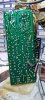
With the tone board pots undone from the front chassis panel, access to both sides is apparent and there is no need to remove the board from the receiver.
All electrolytics replaced with Elna RFS and WIMA MKS2 for 1uF and 2.2uF.
TR01, TR02 2SC1313 > ZTX694B with hFE of 671 & 653 respectively. Watch the pinouts, these are CBE.
IC01, IC02 BA312 originals were retained as they tested fine. I am awaiting replacements PCBs for use in future builds as per this thread. Thanks Lee and Rick.
https://audiokarma.org/forums/index.php?threads/ba312-replacement.973016/
De-fluxed in situ.
Last edited:
F-2617 Mic Amp
A simple board to access and work on.
Caps replaced with Elna RFS for the larger electros, WIMA MKS2 & Kemet stacked film polyester for the <10uF electro and tantalum replacements.
TR01 2SC1313 > ZTX694B hFE 650 (not shown in pic) pinouts again … CBE
IC01 BA312 retained again.
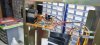
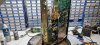

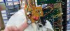
A simple board to access and work on.
Caps replaced with Elna RFS for the larger electros, WIMA MKS2 & Kemet stacked film polyester for the <10uF electro and tantalum replacements.
TR01 2SC1313 > ZTX694B hFE 650 (not shown in pic) pinouts again … CBE
IC01 BA312 retained again.
F-2653 EQ Board
Difficult to access given the fragile green ribbon cables connecting the RCAs. You’ll see in the Driver board post that I eventually replaced them with solid core ribbon.
This board was in a sad state with a lot of oxidation on the input selector wafers and generally dirty.
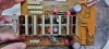
Once the board was removed, I carefully de-soldered the input selector switch, taking care not to snap any bent legs. With the switch removed, access to the components underneath and cleaning the wafer contacts was much easier.
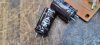
C07, C08 listed as 470uF/50v in the schematic had previously been replaced with 4700uF/10v on the left channel and 470uF/100v on the right. The 10v one was pretty bloated.
All caps replaced with Elna RFS and WIMA MKS2.
IC01, IC02 BA312 retained again.
R17, R18 (56KΩ) and R13, R14 (560KΩ) were heat stressed, out of spec and replaced with 1% metal films of same value.
Input switch reinstalled.
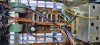
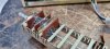
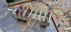
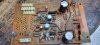

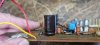

Difficult to access given the fragile green ribbon cables connecting the RCAs. You’ll see in the Driver board post that I eventually replaced them with solid core ribbon.
This board was in a sad state with a lot of oxidation on the input selector wafers and generally dirty.
Once the board was removed, I carefully de-soldered the input selector switch, taking care not to snap any bent legs. With the switch removed, access to the components underneath and cleaning the wafer contacts was much easier.
C07, C08 listed as 470uF/50v in the schematic had previously been replaced with 4700uF/10v on the left channel and 470uF/100v on the right. The 10v one was pretty bloated.
All caps replaced with Elna RFS and WIMA MKS2.
IC01, IC02 BA312 retained again.
R17, R18 (56KΩ) and R13, R14 (560KΩ) were heat stressed, out of spec and replaced with 1% metal films of same value.
Input switch reinstalled.
In later models on the power supply, those 1 Ohm fusible resistors were replaced with 1.5A pigtail fuses for the pair, and 1A for the other. They were soldered in vertically covered in a clear plastic tubing. I wired in remote fuse holders utilizing 3 existing screws mounting the transformer, but of course longer screws to make up for the thickness of the fuse holders. If they did blow, no more surgery needed to replace them. A "one and done" for them. A factory service bulletin and "kit" supplied the fuses, tubing, and stickers for on the board. If you use 1 Ohm resistors there, they should be 1/4 watt so they blow if need be. That's why they were "fusible" to begin with. To protect the transformer.
I decided to work with what I had and to follow Sansui's use of fuses over fusistors. Thanks for the heads up. I made my own fuse holder from protoboard and mounted it to the driver amp bracket. It is easily unbolted from the bracket should the need arise. There is plenty of clearance to the bracket and the driver board and the fuses are still accessible. I’m pretty happy with the result. On reflection, I should have run the wires to the left of the fuse board but it will do for now.
What do you think @Skywatcher ?
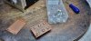

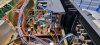
Last edited:
Looks great! As long as the driver board doesn't pick up any AC noise, that will work just dandy.I decided to work with what I had and to follow Sansui's use of fuses over fusistors. Thanks for the heads up. I made my own fuse holder from protoboard and mounted it to the driver amp bracket. It is easily unbolted from the bracket should the need arise. There is plenty of clearance to the bracket and the driver board and the fuses are still accessible. I’m pretty happy with the result. On reflection, I should have run the wires to the left of the fuse board but it will do for now.
What do you think @Skywatcher ?
View attachment 2582956 View attachment 2582957 View attachment 2582958 View attachment 2582959 View attachment 2582960 View attachment 2582961 View attachment 2582962
No noise whatsoeverLooks great! As long as the driver board doesn't pick up any AC noise, that will work just dandy.
F-2619 RF Power Supply
Certainly a hot little board with signs of heat stress to the PCB and C05. It produced more heat than the outputs and can be felt through the wooden case.
I ran with the popular mods below which cooled things down quite a bit.
TR01 2SD313 > MJE15032G
TR02 2SC1211 > KSC2690
TR03 2SC1364 > KSC2383
C01, C02, C04 replaced with Nichicon PW of same values
C05 replaced with Nichicon PW of same value but mounted on the underside of the PCB to distance it from the heat created by the TR01 reg and heatsink
TR01 31˚C (87˚F)
R01/R02 replaced with a single 200Ω 25W chassis mounted resistor, bolted to the large shield separating the front and rear ends of the unit.
The new resistor measured 40˚C (104˚F)
VR01 adjusted to 12.5V between pin 1 and ground, with FM source and Dolby FM on.
BTW, the tuner module was recapped, just not photographed.
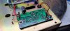

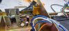

Certainly a hot little board with signs of heat stress to the PCB and C05. It produced more heat than the outputs and can be felt through the wooden case.
I ran with the popular mods below which cooled things down quite a bit.
TR01 2SD313 > MJE15032G
TR02 2SC1211 > KSC2690
TR03 2SC1364 > KSC2383
C01, C02, C04 replaced with Nichicon PW of same values
C05 replaced with Nichicon PW of same value but mounted on the underside of the PCB to distance it from the heat created by the TR01 reg and heatsink
TR01 31˚C (87˚F)
R01/R02 replaced with a single 200Ω 25W chassis mounted resistor, bolted to the large shield separating the front and rear ends of the unit.
The new resistor measured 40˚C (104˚F)
VR01 adjusted to 12.5V between pin 1 and ground, with FM source and Dolby FM on.
BTW, the tuner module was recapped, just not photographed.
Last edited:
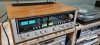
This was my first Sansui Dolby receiver restoration. I am forever grateful for all the others who have shared their experiences with the 8080DB (and 9090DB). I have tried to leverage the best of what I could find on AK, given timescales and budget and hope I have done this unit justice. Note, the case is a work in progress.
I am truly blown away with the SQ through every input but especially Dolby FM. This is why I am a Sansui tragic!

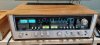
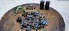
I am truly blown away with the SQ through every input but especially Dolby FM. This is why I am a Sansui tragic!
Last edited:


Scott Muni
Well-Known Member
It's crazy how much heat comes off R01/02. I also moved to a single resister on the metal plate along with thermal paste. Also installed a stick-on alloy heat sink to the back side of the metal plate.
New resister still throws the heat, but it gets dissipated quickly.
New resister still throws the heat, but it gets dissipated quickly.
Scott Muni
Well-Known Member
Is that AU555a to the left of the 8080?This was my first Sansui Dolby receiver restoration. I am forever grateful for all the others who have shared their experiences with the 8080DB (and 9090DB). I have tried to leverage the best of what I could find on AK, given timescales and budget and hope I have done this unit justice. Note, the case is a work in progress.
I am truly blown away with the SQ through every input but especially Dolby FM. This is why I am a Sansui tragic!
View attachment 2583699 View attachment 2583700 View attachment 2583701 View attachment 2583702
Yes. It is number 39 and now sold. I have number 40 on the bench. My restorations are based on @Leestereo but with all new components of every kind including all resistors. Amazing sounding units. Can't believe I've done so many!!Is that AU555a to the left of the 8080?
Last edited:
Scott Muni
Well-Known Member
Wow 40 units! I just finished one, did the lee upgrades. Really nice sounding amp, and so easy to work on.

Your mods are legendary Ben! I've also done a few of your 717 designs. Absolutely love your work.@BradWil: Was the 555A the most popular amplifier in Australia? Forty restored and upgraded 555As, that is impressive! Now where did I put that patent application...
There sure seems to be a lot of 555As here. I'd say 50% were customers and the rest my own stock over a few years

absolve2525
Super Member
Great job! Thanks for posting pics and your process!
This was my first Sansui Dolby receiver restoration. I am forever grateful for all the others who have shared their experiences with the 8080DB (and 9090DB). I have tried to leverage the best of what I could find on AK, given timescales and budget and hope I have done this unit justice. Note, the case is a work in progress.
I am truly blown away with the SQ through every input but especially Dolby FM. This is why I am a Sansui tragic!
View attachment 2583699 View attachment 2583700 View attachment 2583701 View attachment 2583702
I'm going to have to make an order for all these parts i wonder if you have like a digikey cart
I don't unfortunately, however if you visit https://tolisdiy.com/2019/02/23/san...rrection-creating-a-modern-f2624-replacement/ you can get all the info on the legendary ToliToms F-2624 PCBI'm going to have to make an order for all these parts i wonder if you have like a digikey cart

ImWolf
Active Member
Novice question for you: In the past I've replaced caps on computer MB's and on my engine lathe, and every source at the time told me to always match the original uF, but I can increase voltage to anything so long as the form factor of the the new capacitor doesn't become an issue. So why didn't you follow this "rule" repairing this receiver?Filter Caps
The original 12,000uF/63V NCC items were replaced with 15,000uF/63V Nichicon LKG series, with a matching 40mm diameter.
Thanks,
Wolf