• The move to the new server is done. There are some software and database maintenance updates in process. This has us passing the hat around to help out. We appreciate any donations. Seriously, even a dollar helps. The payment page may be found here - https://www.audiokarma.org/support.html

Sansui 9090 W/O Working Tuner/Dial Lamps/Meters

JJCalvillo

AK Subscriber
Subscriber
Getting good balanced sound out of Aux, Tape1 & 2, but nothing from AM/FM. No meter movement and no lamps at all. This came in like this.

Tested Emitter of TR01 on F2431 and it was good at 12.65 Vdc. Schematic shows the 12.6 Vdc leaving F2431 at post 01 and going to "B11/Post18 on F2549, where I found 0 Vdc.

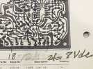
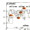
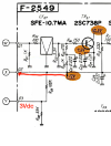
So I traced the red wire coming from the Em of TR01 on F2431 and instead of going to B11/post 18 as on the schematic, it goes to an unmarked post next to the screw on the corner of F2549. See photo below. Traces connect the post to points 1 (jumper wire to unmarked connection on the board just past the middle screw) and 2 (jumper wire).

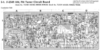
Bottom line this F2549 is NOT the same board as the schematic or diagram. Second photo, of the board diagram, shows a connection from the post the red wire from F2431 is connected to jumped to "B11"/Post 18. Connection to post 18 is not there on my board.

Are there different versions of F2549, and are there corresponding schematics/board diagrams?

IMG_2342.JPGF2549Diagram.jpeg
 
Last edited:
Register to hide this ad
Now I'm finding the 12.7 Vdc one pin to the right of the pin #18 on the diagram, #19 printed on the diagram. So doesn't match the schematic.

Edit: Owner says the lights, tuner, and signal/tuning meters all went kaput at once. Not finding a blown fuse.
 
Last edited:
Went to F1519 (front end?) looking for 12 Vdc on post #4. No electrons on either the yellow or white. Guessing Yellow is where it's supposed to live.

IMG_2346.JPG
 
@analogwisdom made a good catch. I am using the 9090db diagram for the info below.

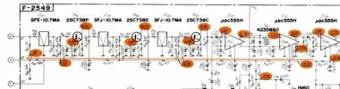
Back up a bit from the front end pack. The 12 volts you are looking for comes from the F-2549 pin 03 (point Y).
I'm pretty sure the yellow wire is not the one you are looking for.

If you don't have that 12 volts on pin 03 then the power for the whole FM IF strip is in question.

909012.jpg

There are several resistors on that 12 volt line that could be open if the 12 volts at pin 03 is missing.

9090if.jpg
 
Will get on this as soon as I get the miniature owl out of the wifes potting bench. Thought I had all day to spend on it, and Mabel finds an owl.
 
Owl flew the potting bench, don't have to haul it to the bird peeps.

So there's about 100mVdc on your choice of the three posts w,x and y. Went back to R33 and there's good juice there. Working toward the posts.
 
Resistors in line are getting voltage going downstream towards the w, x, z posts until R17, which is empty, no resistor or jumper. Can it be as simple as putting a 4.7 ohm .25 watt resistor in at R17?
 
Resistors in line are getting voltage going downstream towards the w, x, z posts until R17, which is empty, no resistor or jumper. Can it be as simple as putting a 4.7 ohm .25 watt resistor in at R17?
That is really really strange. Do you know if it ever worked? Does it look like the trace side of the circuit board has been worked on around R17?

Yes it could be that simple if somebody has been in there before you. X and Y will be the only ones with voltage, W is the IF signal from the tuner pack.
 
Dosen't look messed with. The holes are capped with what looks like original solder as though it's been that way from the factory.

Owner said the meter, lamps and sound from the tuner all crapped out at the same time. Like a part blew.
 
Put the resistor in and the meters came to life, both S.S. and Tuning work as you tune stations. No sound or lamps.

Edit: Also got:
W = 40mV
X = 12.2V
Y = 3.15V
 
Went back and measured again because it looks from the schematic like X (#2) and Y (#3) have their voltages crossed. 12V on one side of R09 and 3Vs on the side next to X, but I get 12V at X (middle post, #2).

Y (#3) shows 12V on the schematic at post Y on F2549 and on F1519, but on board F2549 Y tests the 3V the schematic shows on X (#2).

Wonder if this is why they left R17 out, and they had the correct voltages via another path before a part crapped out screwing up the works.

Anyway
 
Assuming our service data is correct. Not always. With R17 missing the first IF amp would have no power, and more importantly the tuner pack would have no power.

If the system looks unmolested I don't see how it could have worked.

The only left field plausable WAG thing I can think of is that the leads of R17 did not go all the way through the board and were barely held in by the solder. How did it fall out and where did it go. Gravity would have held it in place if my WAG is true. Did the owner move it and then it quit?

I have seen one leg of components just barely soldered and not going through the board but never two. You get all the fun ones.

Again assuming the schematic and the connection dots are right. We know Sansui manuals have mistakes.

9090tun.jpg.

You have a voltage divider with R8 and R9. With twelve volts in you will get 3 volts out, supposedly at pin 2, going to X on the tuner pack. That is the AGC voltage

Pin 3 of course should have the full twelve volts going to Y on the tuner pack.


Now on to the loss of sound. What lights are not working?
 
Wait!

The 12V gets knocked down by R09/100K on the way to post 2 (X), but if you look at the board diagram it looks like R09 is connected to post 3 (Y) which would explain why I'm getting 12V on post 2 (X) instead of 3V. Also nothing between R17 and post 2 (X) means it would get the whole 12 V I'm seeing.

Went and tested and R09 is connect to post #3 (Y), also in circuit it measures 25K. R17 mainlines into post 2 (X) and that's why we're getting 12V at post 2 (X).

Also, when I tested this time I gave it a little more juice and we are getting week sound from FM.

Edit: Would the weak sound be a bad transistor/s not amping the signal?
 
Last edited:
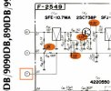
I changed the schematic (R09 & R08) to show what's actually happening on the board. It matches the board diagram, R09 is actually cutting the V to post 3 (Y) instead of post 2.
Added the board diagram which is accurate it for posts 2 and 3 with reference to R08 and R09, and voltage.

F2549A copy.pngSansui9090DB TunerBd.png
 
Only lights that work are on the power meters.
All of the lamps are powered from the same supply, so that must be OK. How about the source lamps?
Perhaps a power surge took out all the fuse type lamps?

8/1/25 Edited post to remove 9090DB references. We are working on a 9090 not a DB.
 
Last edited:
I changed the schematic (R09 & R08) to show what's actually happening on the board. It matches the board diagram, R09 is actually cutting the V to post 3 (Y) instead of post 2.
Added the board diagram which is accurate it for posts 2 and 3 with reference to R08 and R09, and voltage.

View attachment 3564410View attachment 3564411
Good catch on the board. You can certainly see what is going on with the traces.
 
Back
Top Bottom