• The move to the new server is done. There are some software and database maintenance updates in process. This has us passing the hat around to help out. We appreciate any donations. Seriously, even a dollar helps. The payment page may be found here - https://www.audiokarma.org/support.html

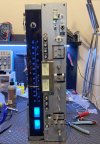
Sansui 9090 W/O Working Tuner/Dial Lamps/Meters

That’s what I thought.
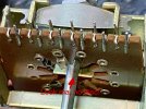
Well you are in for a treat. Those switch contacts can be pretty delicate and easily bent or broken by the center disc if out of position or the contacts are too high or too low.

They can be fixed but it is a delicate job if you have to realign or tension the contacts. You can desolder and remove just one wafer. You do have to bend the tabs on the metal frame and pull the shaft out the back. Take pictures, take notes, mark wafers whatever so you get things back in sync when you put it back together.

You can see the tabs @kwayde pointed out that need to bent away to free the wafer.
The shaft will pull out the back, it is just a friction fit in the front. You need to remove the large filter/decoupling caps behind it to make room
PXL_20240331_154905494.jpg


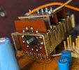
Here is a wafer form a 9090 I worked on. Someone else had hacked it up pretty bad

The tension of the yellow contact was very low and the red contact got pushed/bent to where it was below the rotating contact.

You can see on the right side where some of the rivets are soldered over. That is a fix for the corrosion that takes place between the contact and the trace.
In this case they did a half ass job. Do them all if you do any. Check top and bottom, the trace is not always on the contact side.

You need to be sure you get a good solder job. Clean, clean again and use flux.

PXL_20240331_160639193~3.jpg
I ended up replacing the red contact, it just would not hold tension after bending it back.

I have seen that eBay switch before, looks like it might be a good solution.
 
Last edited:
@kwayde thanks for you photo, it solves the mystery. I was told this unit hadn’t been worked on, but have found several signs it has. Another is the complete absence of a rotary disc on the switch. It bent some of the tabs before departing the scene.

Does the shaft of the switch go through the middle of the disc, is it possible to just “fall off”?

View attachment 3566116
Missed this part.
Another is the complete absence of a rotary disc on the switch. It bent some of the tabs before departing the scene."

That would explain the source lamps not working. The front wafer controls those.
 
Guy swears this has never been in for service. This is the front wafer. If you look close you can see the contacts on the wafer are pretty beat.

9090SelSwSideA.JPG

9090SelSwSideB.JPG
 
Let us know how it is! I just finished a 9090 for someone and I disassembled the switches to clean. It was not fun. Knowing a replacement exists would have made me a lot less nervous about potentially screwing up.
 
Looking at switch now from the seller mentioned above. It does look like quite a bit of work went into assembling the switch. I count 6 small pcbs. two are just pin board, the exterior one has several surface mount semis on it. The pot inside is kind of floating, like it's held by wires inside, I think that will help when mounting it, it can ease into the best position for no stress on all of the parts. Looking forward to your test of it.
 
PROGRESS! The new Selector Switch was pretty simple to install, the hardest part being getting all the pins in alignment to go into the board.

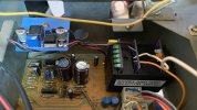
WEAK volume outta the tuner, I'm getting FM, but it is still very weak and the Stereo indicator is NOT lighting. Since all the other lights now work, I'm NOT betting on a dead lamp.

Aux and both Tape inputs play expected volume, I'm pretty sure the problem's on the 9090DB Tuning Board.

9090FuncSwitch.JPG
 
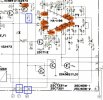
It may be the FM muting circuit(s)

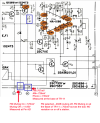
Check pin 36 for a voltage change when going to and from FM on the selector. I believe pin 21 goes to the muting on/off push button.

Voltage on the base of TR10 and 11 will short the FM audio outputs to ground for muting.
Several ways it can happen.
Via TR07 from pin 21 through D10 to the base of TR07 for manual muting on/off.
From TR06 to the base of TR07 for automatic muting. I cut it off but to the left of TR06 is where the interstation muting adjustment pot is.
From pin 36 which should mute the FM when the selector is in AM mode.

With the selector in FM mode and the manual muting push button off there should be no voltage on the bottom of R61. Or the Bases of TR10 & 11.
In auto muting mode it should turn on/off between stations or tuned to a weak station.


909tunmut.jpg
 
Yes, would rather buy a new switch than pay through the nose for an original that may be about to tip over anyway.
If you are the owner it is probably a better deal $ wise than paying a tech to attempt to fix the original switch. The tech may or may not be successful. That new switch pretty much guarantees a long term working repair. Certainly better than the original switch, the sealed relays should provide a better path than the original contacts and wont' get dirty or corrode.
 
Last edited:
Fixing it for the original owner. Still no clue who “worked on“ the factory switch. Have an 8080 I’d buy this switch for.
 
Finally got to take some measurements.

When I put the -20dB muting ON, the FM volume go to zero. So it works, but the volume is so weak -20dB completely cuts the sound.

9090FMmuting.png
 
Finally got to take some measurements.

When I put the -20dB muting ON, the FM volume go to zero. So it works, but the volume is so weak -20dB completely cuts the sound.

View attachment 3570207
Those voltages on M don't jive with what I think is going on. (could be VBE drop on TR10 or TR11 if they are on with voltage from TR07.)

The 8080/9090 schematic is a bit hectic to unravel sometimes. Either way it seems to be just on the verge of being high enough voltage to trigger TR10 and 11 on. You could try taking either TR10 or 11 out, or both if you feel adventurous and see if one or both of the channel come alive.

Or pull one end of R61 and see what the behavior is.
 
Back
Top Bottom