

You are using an out of date browser. It may not display this or other websites correctly.
You should upgrade or use an alternative browser.
You should upgrade or use an alternative browser.
Sansui AU 20000 restoration - many... many pictures
- Thread starter Kale
- Start date


Kale
Super Member
Kale - you are a master audio restoration craftsman and storyteller.
Here at this forum, I heard many positive names about my work, BUT for first time someone told to me that I am storyteller

It is really a great progress for me

Ok, ...I am going to show you more...
Look what I have found
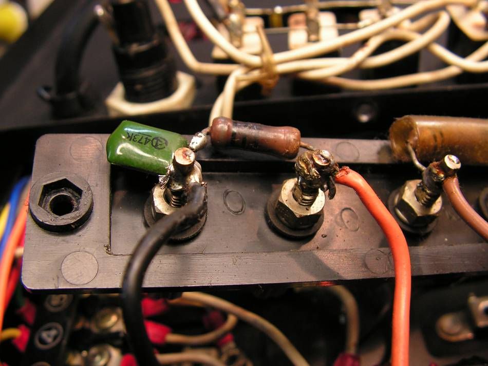
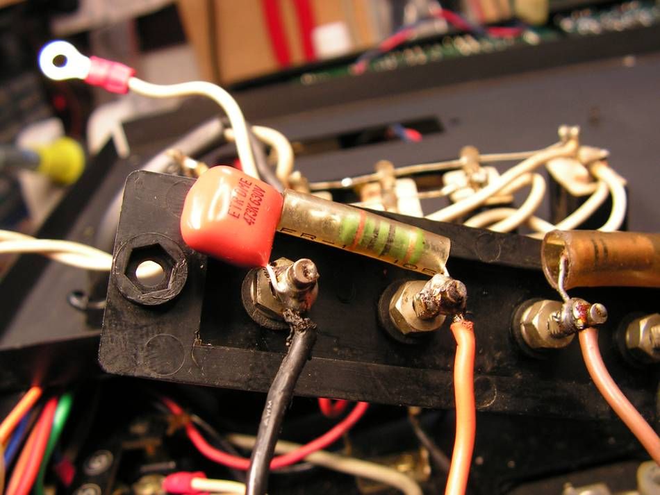
that Zobel filter was burned out, and what is interesting, the burned resistor was not original :scratch2:
OK, it is fixed
Last edited:

 ara:
ara: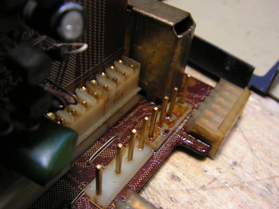

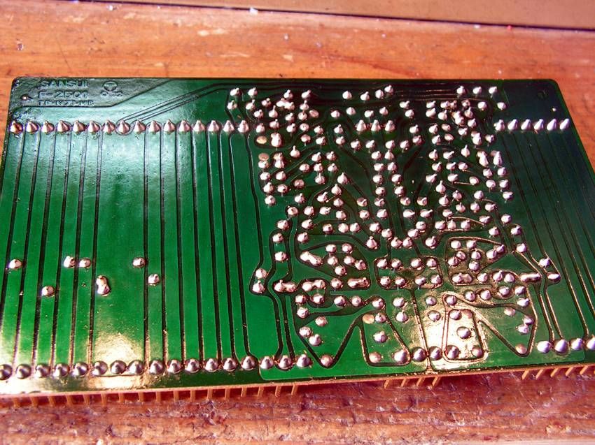
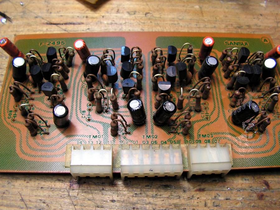
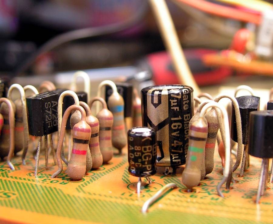
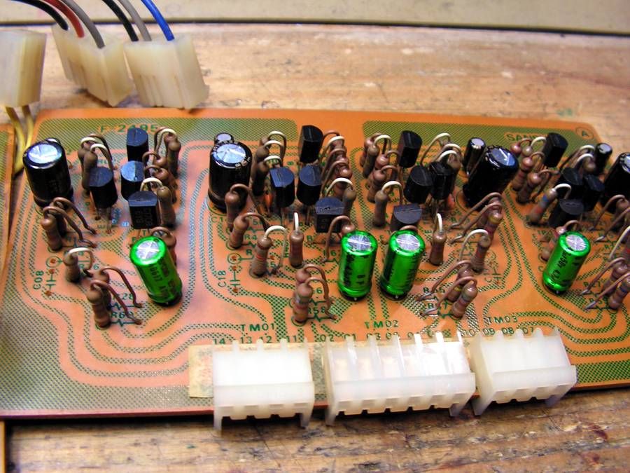
Kale
Super Member
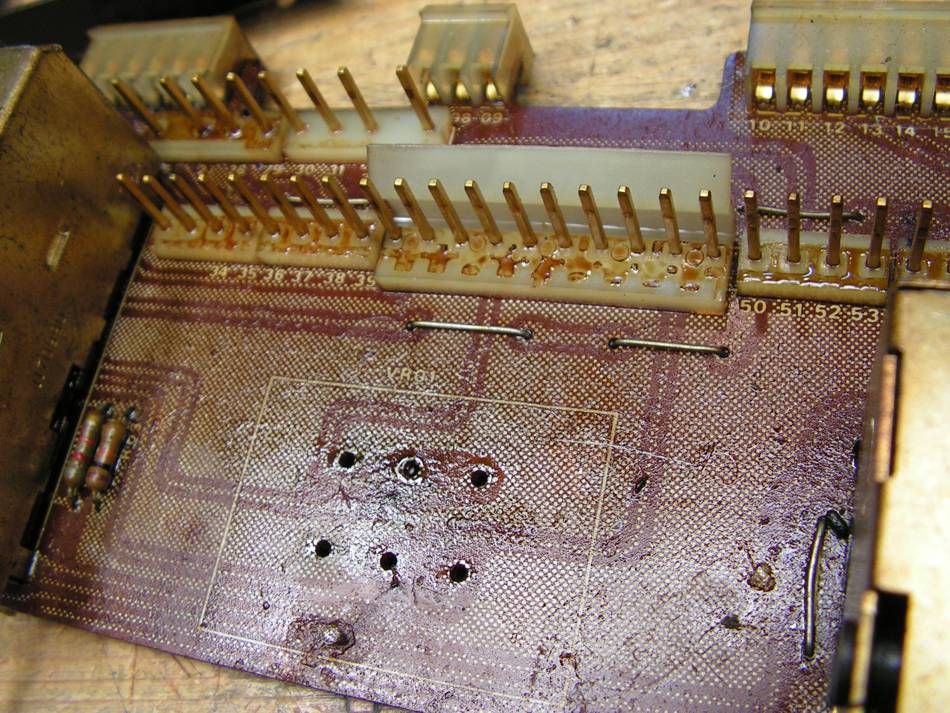
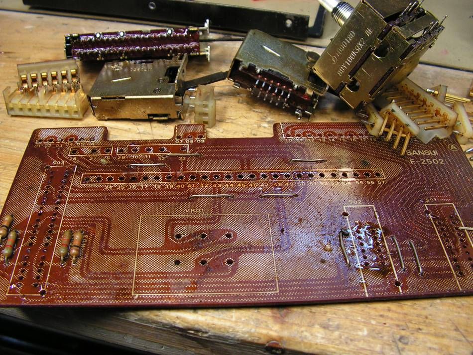
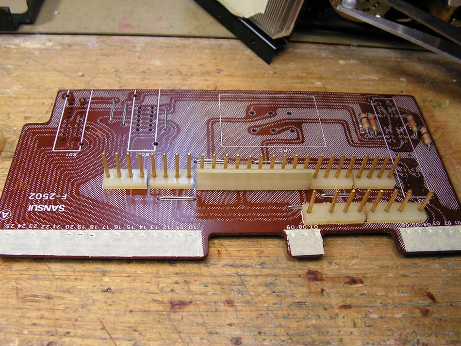
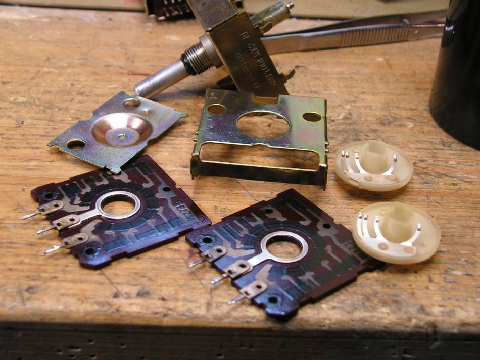
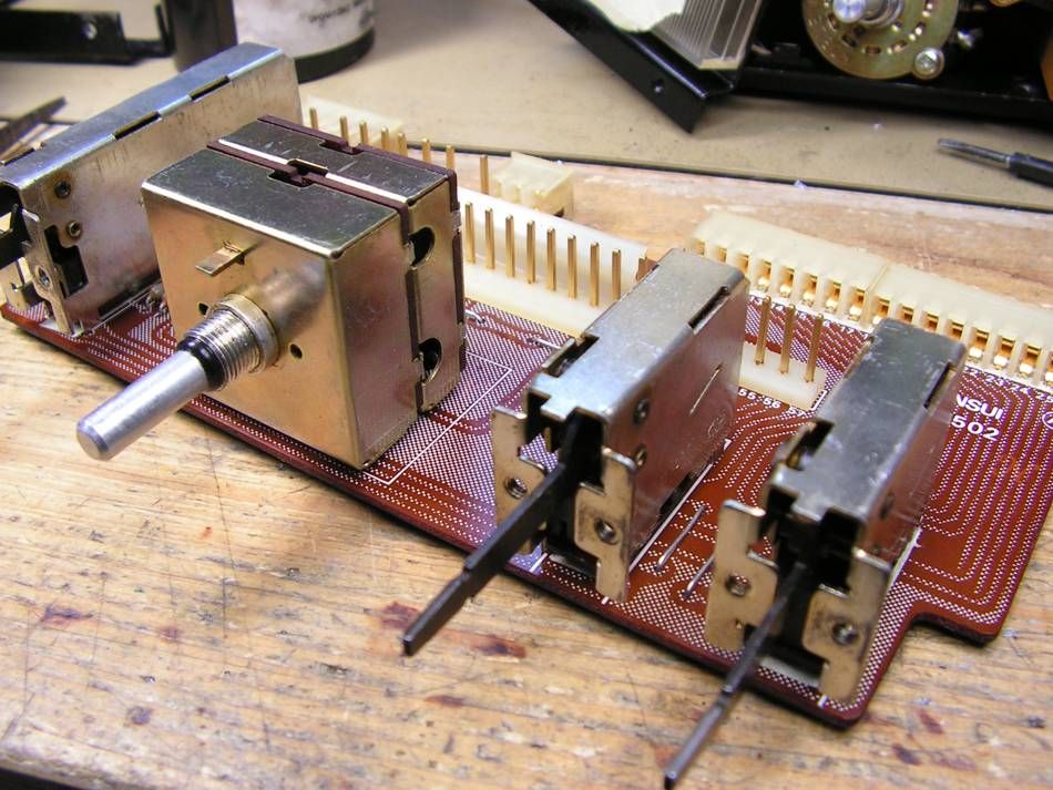
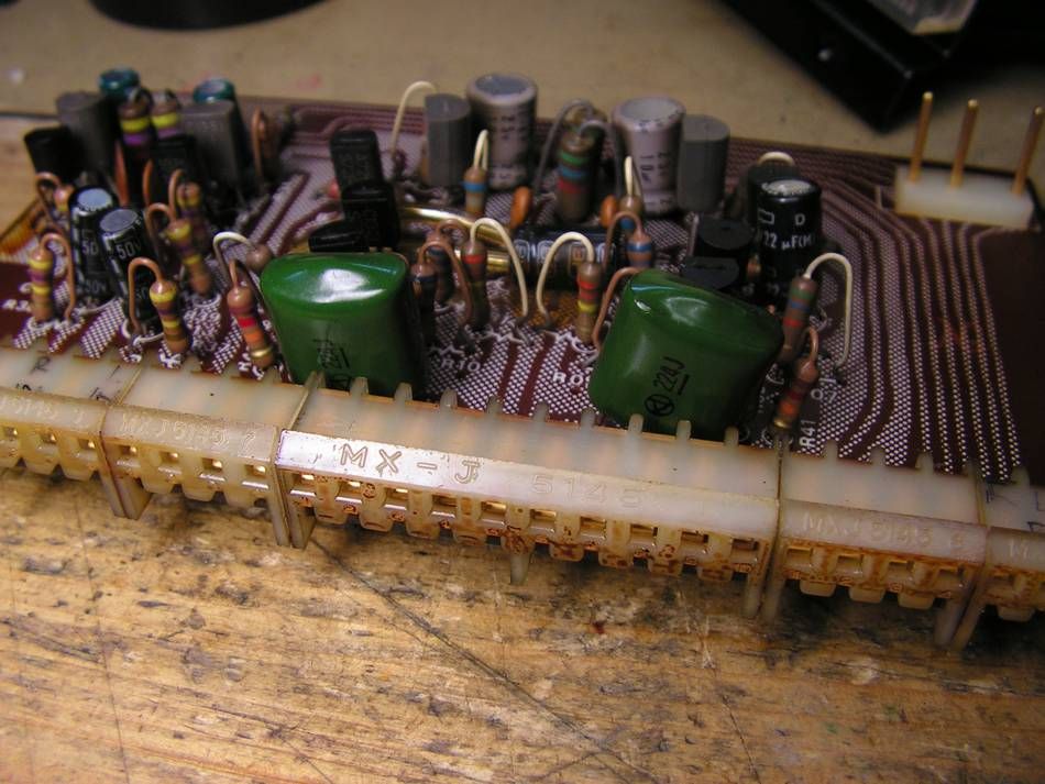
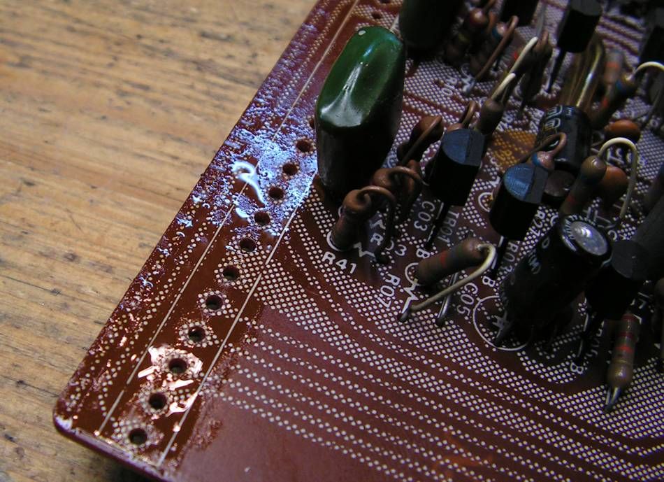
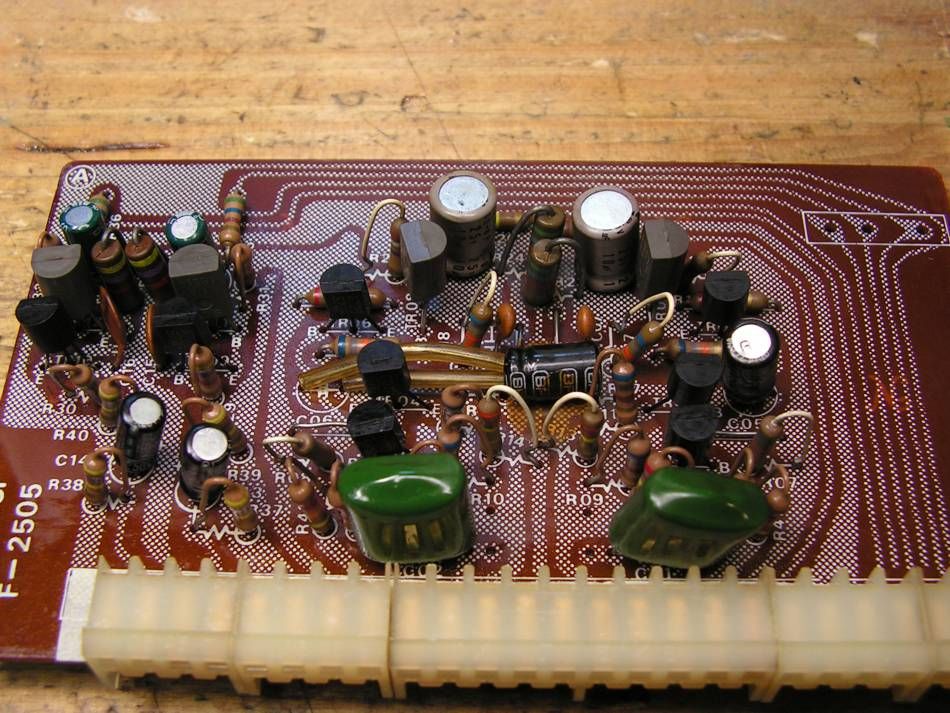
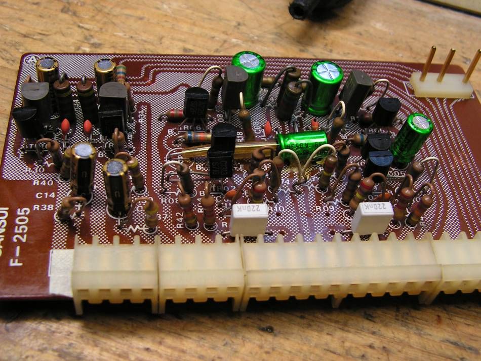
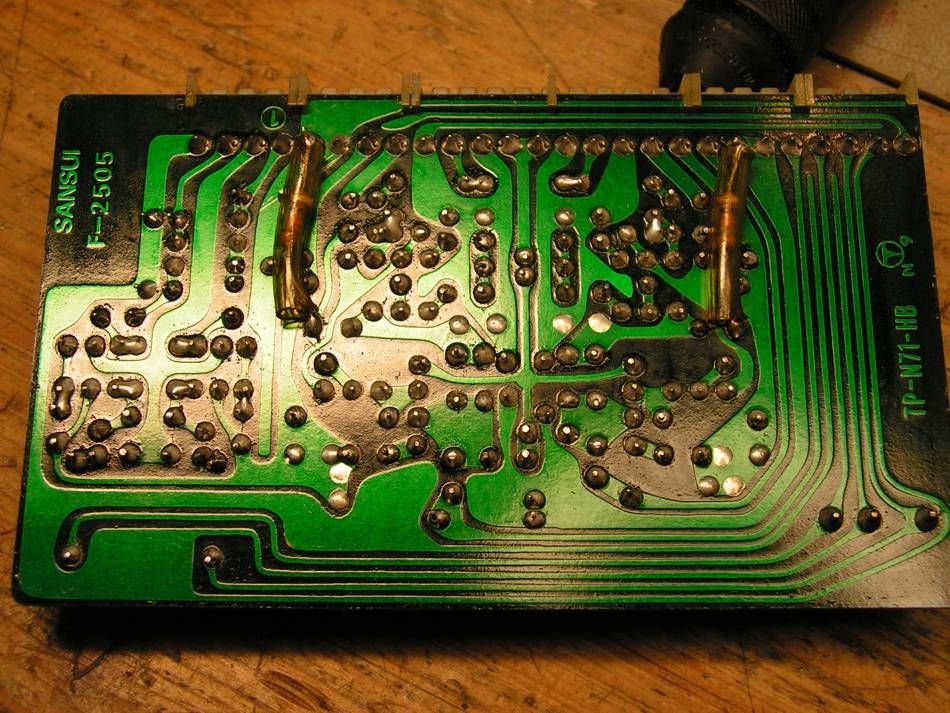
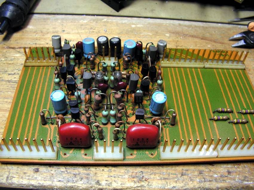
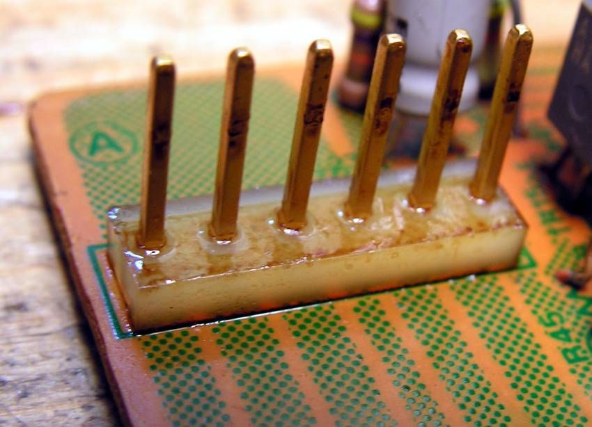
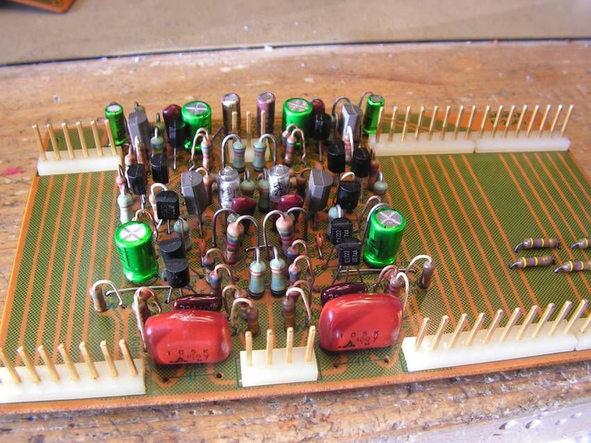
... Filter Board...
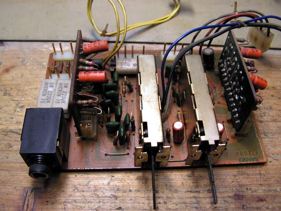
ready for cleaning
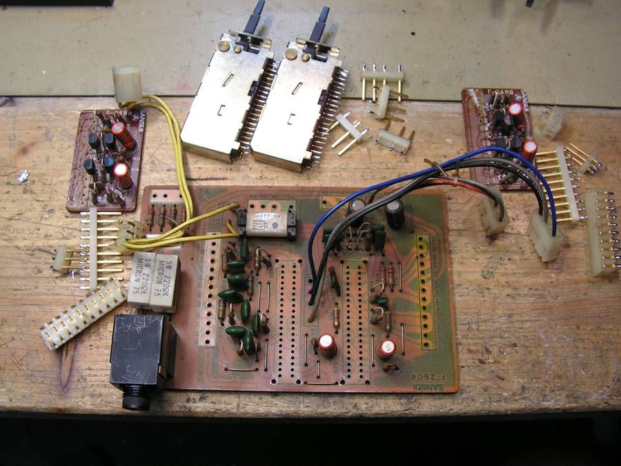
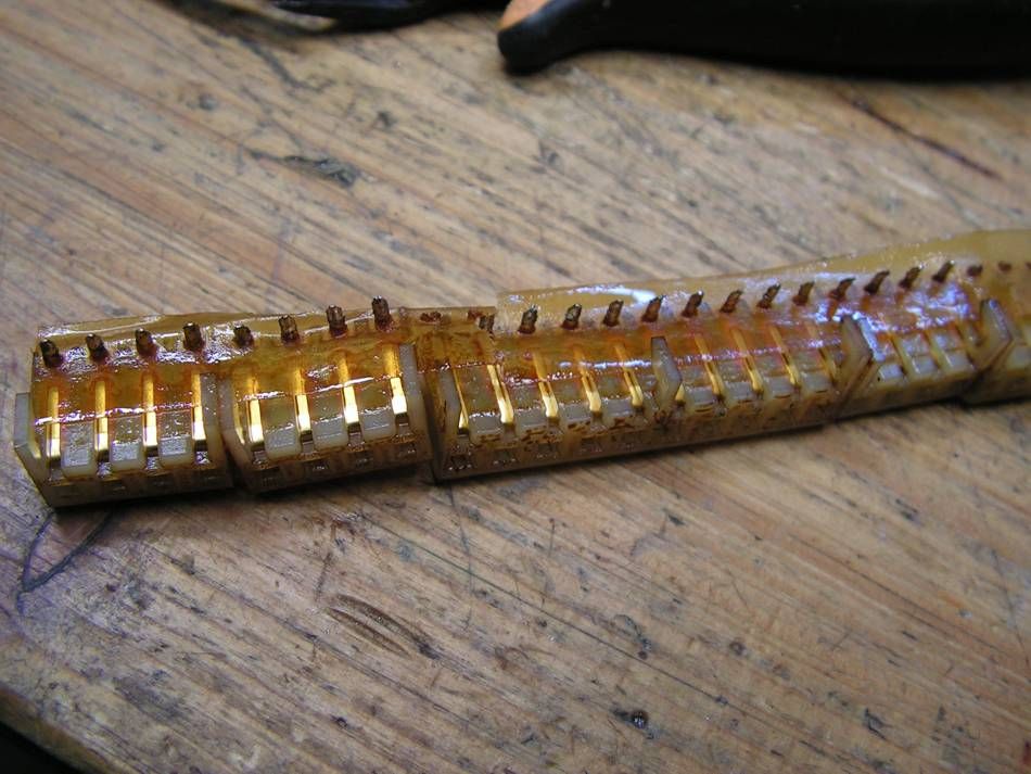
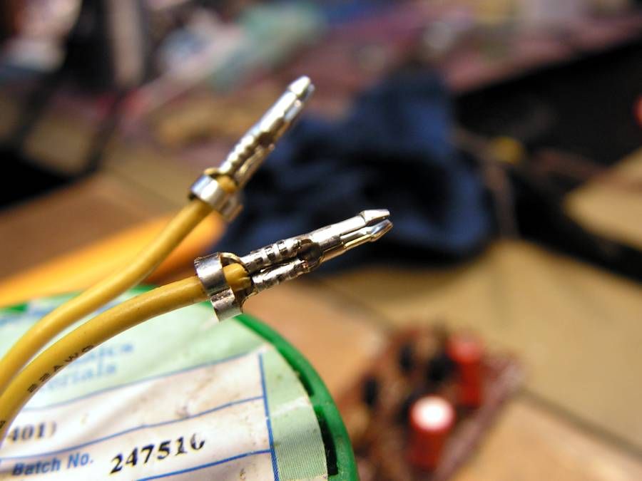
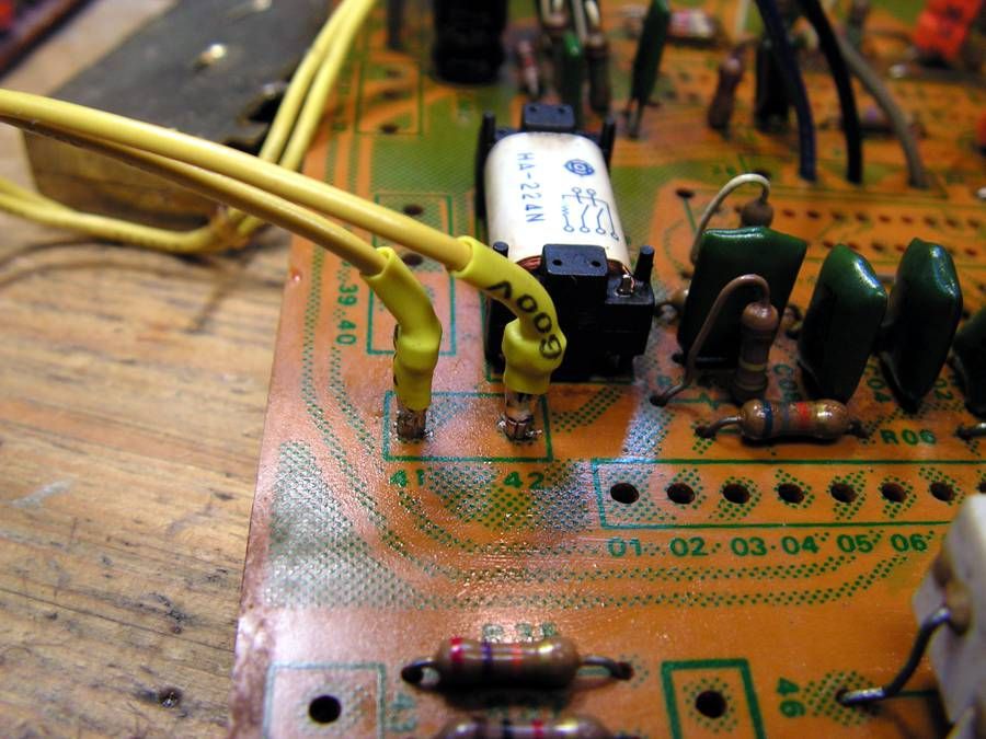
but here I have fount that yellow cable was broken because it was soldered directly to board, so I decided to connect it on that way
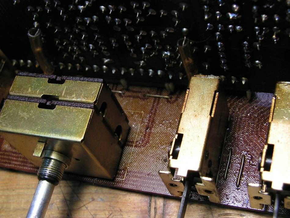
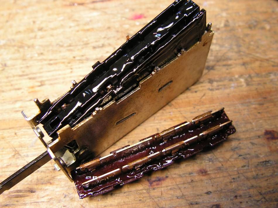
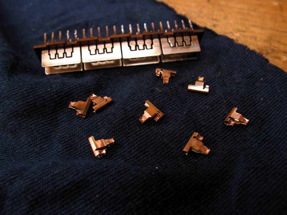
... cleaning the switch
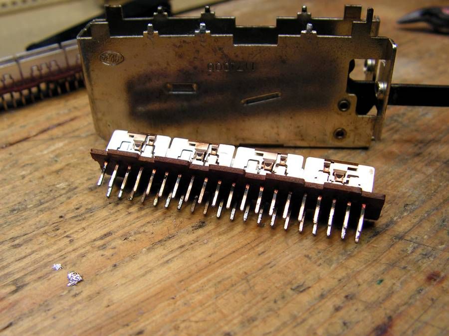
and checking crossover resistance
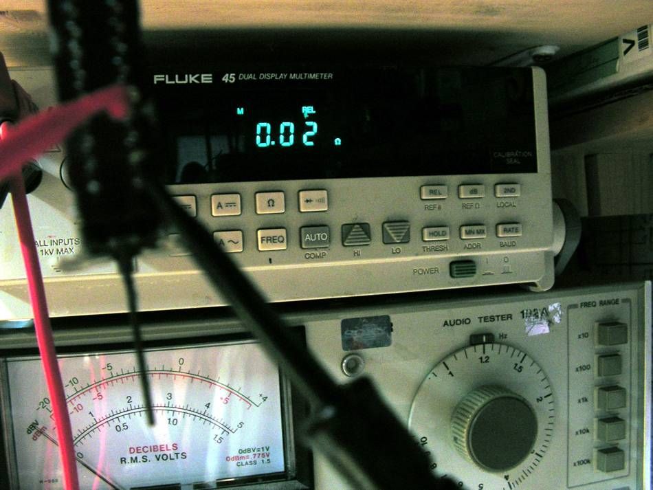
that FLUKE has feature to measure very small resistance without cable influence.
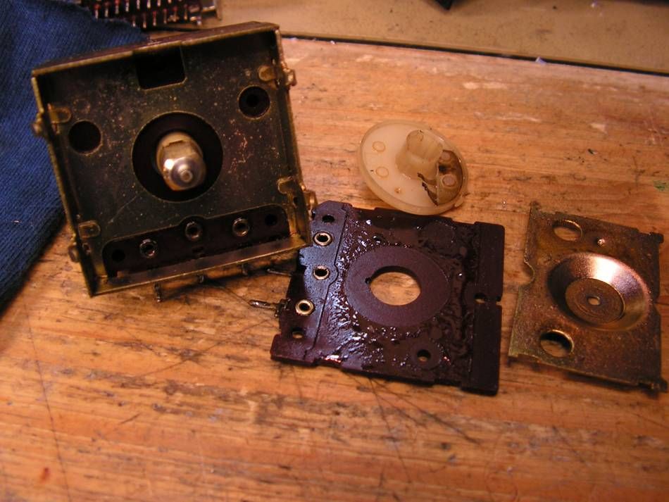
... more cleaning...
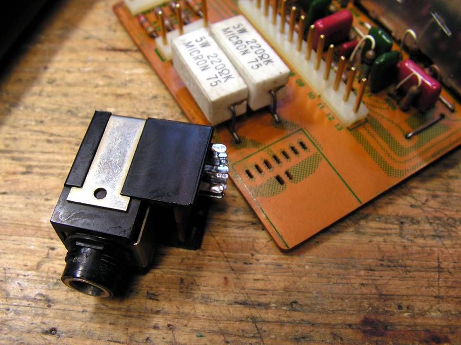
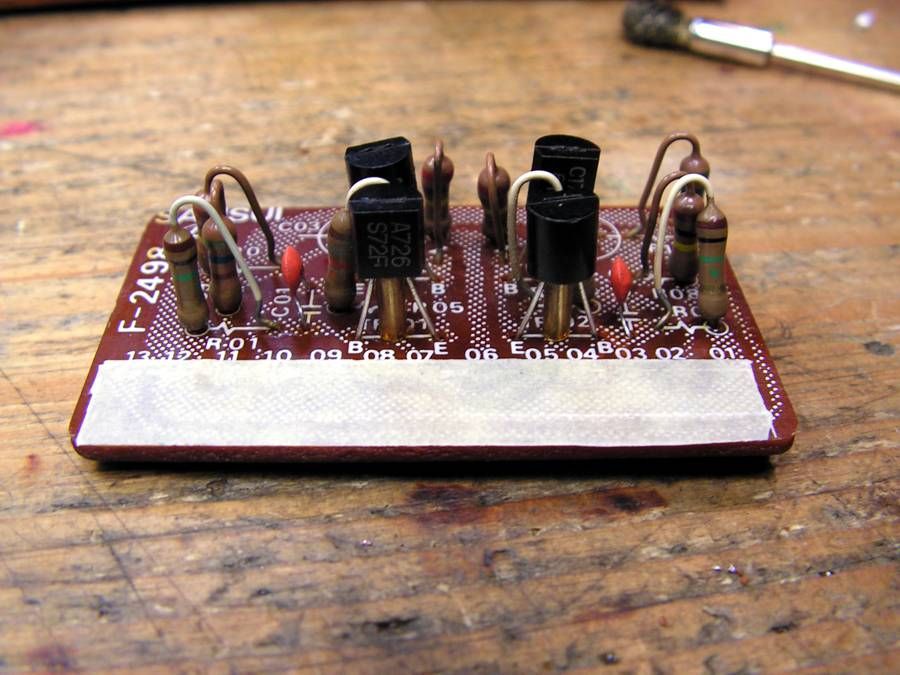
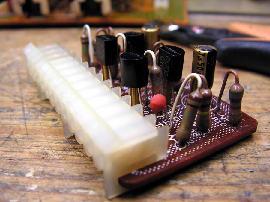
and finally
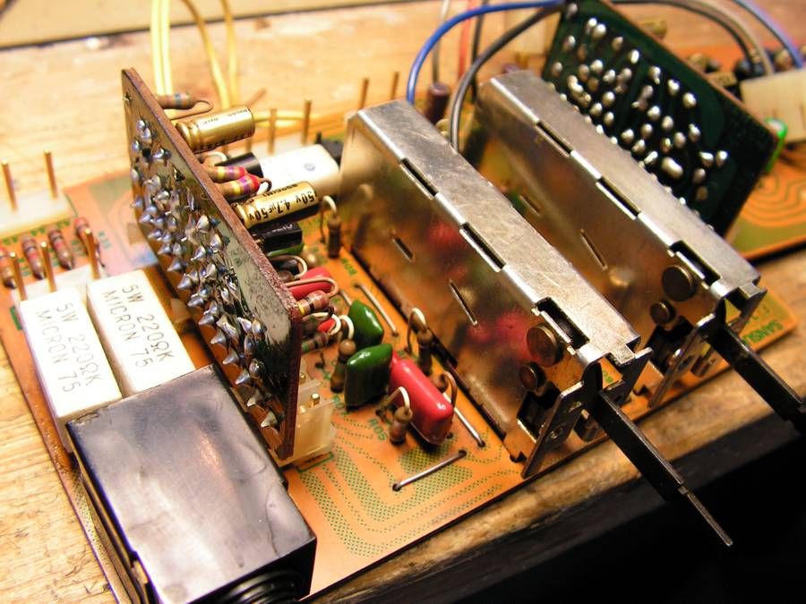
ready for cleaning
but here I have fount that yellow cable was broken because it was soldered directly to board, so I decided to connect it on that way
... cleaning the switch
and checking crossover resistance
that FLUKE has feature to measure very small resistance without cable influence.
... more cleaning...
and finally

DVNOBLE
New Member
Au-20000 some differences.
Hello Friend! Great job! My AU-20000 is different from yours.
The plates f-2507 does not have the TR-12, and he does not appear in the schematic.

In your temperature control is done in drivers and mine is done in the output transistors.


I would also ask what is the value of two resistors r11 and r14 of porcelain that are on the underside of the plate f-2512.
In my 120rx5w they are connected in series and 150rx5w right on the board.


You know there are two generations of au-20000? What is it the oldest mine or yours?


Hello Friend! Great job! My AU-20000 is different from yours.
The plates f-2507 does not have the TR-12, and he does not appear in the schematic.
In your temperature control is done in drivers and mine is done in the output transistors.
I would also ask what is the value of two resistors r11 and r14 of porcelain that are on the underside of the plate f-2512.
In my 120rx5w they are connected in series and 150rx5w right on the board.
You know there are two generations of au-20000? What is it the oldest mine or yours?
Last edited:


xoaphexox
Supernatural Anesthetist
Nice thorough job. Restoring to this degree is certainly a labor of love - a love that I and many others here share with you.
Thanks for letting us look over your shoulder as you sort out this amp. It is indeed a great amp - maybe the best vintage integrated Sansui had to offer aside from perhaps the AU-919, which is also a challenge to restore.
Thanks for letting us look over your shoulder as you sort out this amp. It is indeed a great amp - maybe the best vintage integrated Sansui had to offer aside from perhaps the AU-919, which is also a challenge to restore.
Kale
Super Member
@ DVNOBLE
I must say you, you have very interesting model of AU20000 amplifier. Those pictures are new to me... I see some restoration job was done on yours amp, but when I see yours pictures, many differences I can see, especially on regulated power supply board... maybe someone did some modification... but those ceramic resistors made by Micron, just as Sansui used... really interesting, but unfortunately I cant help you.
One interesting detail I can see on yours picture; module of power stage doesnt has connector which goes into Motherboard for Driver board, the wires of power stage module are soldered directly on the board!?!
I have pictures of restoration two AU2000 and two BA3000 what I did in the past, but noones has that kind of boards like yours.
I must say you, you have very interesting model of AU20000 amplifier. Those pictures are new to me... I see some restoration job was done on yours amp, but when I see yours pictures, many differences I can see, especially on regulated power supply board... maybe someone did some modification... but those ceramic resistors made by Micron, just as Sansui used... really interesting, but unfortunately I cant help you.
One interesting detail I can see on yours picture; module of power stage doesnt has connector which goes into Motherboard for Driver board, the wires of power stage module are soldered directly on the board!?!
I have pictures of restoration two AU2000 and two BA3000 what I did in the past, but noones has that kind of boards like yours.
Last edited:

canuckaudiog
On a quest for high fidelity
Awesome work.
It makes me wonder what my amplifiers look like deep inside.
It also gives me confidence to maybe try a full restoration like you have done one day. Again, amazing work Kale!
It makes me wonder what my amplifiers look like deep inside.
It also gives me confidence to maybe try a full restoration like you have done one day. Again, amazing work Kale!
DVNOBLE
New Member
@ DVNOBLE
I must say you, you have very interesting model of AU20000 amplifier. Those pictures are new to me... I see some restoration job was done on yours amp, but when I see yours pictures, many differences I can see, especially on regulated power supply board... maybe someone did some modification... but those ceramic resistors made by Micron, just as Sansui used... really interesting, but unfortunately I cant help you.
One interesting detail I can see on yours picture; module of power stage doesnt has connector which goes into Motherboard for Driver board, the wires of power stage module are soldered directly on the board!?!
I have pictures of restoration two AU2000 and two BA3000 what I did in the past, but noones has that kind of boards like yours.
This model is the Japanese 100v. Those changes were that I did, because the heat was damaging the card.
From what I checked they confer circuit with the service manual that is in hifiengine.com.
Those wires were already so when I picked up was probably done to avoid poor contact.
I replaced all the resistors and capacitors eletrolitic him. Reducing the cutoff of 10Hz to 2Hz.
Where are your photos from BA-3000?
Hug!


Last edited:
Kale
Super Member
@ DVNOBLE
Yours pictures are so large, please can you resize them? It will be easier to see them, on that way the structure of thread is distracted...
About yours question; I didnt say that I have pictures of BA 20000, I have pictures of restoration two BA3000
EDIT: Now it is much more better when yours pictures are resazed
Yours pictures are so large, please can you resize them? It will be easier to see them, on that way the structure of thread is distracted...
About yours question; I didnt say that I have pictures of BA 20000, I have pictures of restoration two BA3000
EDIT: Now it is much more better when yours pictures are resazed
Last edited:

kevzep
Its all about the Music
Nice work Kale, looks like the previous "technician, or butcher" used whatever screws they had lying around to secure one of the output transistors!!
I like the work you do to clean up the circuit boards, dismantle and clean the switches....
I also like those emitter resistors you are using.......
I am a bit confused though, we seem to now have some other restoration with some VERY large pictures....its making the restoration thread a bit confusing.....
I like the work you do to clean up the circuit boards, dismantle and clean the switches....
I also like those emitter resistors you are using.......
I am a bit confused though, we seem to now have some other restoration with some VERY large pictures....its making the restoration thread a bit confusing.....

DCinDC
I'm here to fix it
@ DVNOBLE
but when I see yours pictures, many differences I can see, especially on regulated power supply board... maybe someone did some modification... but those ceramic resistors made by Micron, just as Sansui used... really interesting, but unfortunately I cant help you.
One interesting detail I can see on yours picture; module of power stage doesnt has connector which goes into Motherboard for Driver board, the wires of power stage module are soldered directly on the board!?!
Haven't read the whole thread yet, but wanted to say to Kale that I have two different reg ps boards here and a couple of AU-20ks that have the output stages soldered on instead of the gold plug in pin assys.
We also know there are two different output stages, 1 with bias transistor on it, 1 without. Same for the driver boards, where the bias transistor moved from/to.