

You are using an out of date browser. It may not display this or other websites correctly.
You should upgrade or use an alternative browser.
You should upgrade or use an alternative browser.
Sansui AU-919 Black Flag Capacitors, Some help please
- Thread starter sjackh
- Start date


TupolevFan
Super Member
in copy of SM i have i can't see anything on that picture it is blurry.Yes, a lot better picture. Although batter looking at the service manual of the AU-919 it looks like they want the eyelet next to it ( from the emitter pin?) but I am not sure, it's really difficult to see.
 )))
)))But it seems to me each pair of transistors are located vertically on that heatsink not horizontally and i will need to use both sides of heatsink. I measured resistance between those eyelets and it is very high but should not be more than 1 Ohm
Last edited:

Actually the connection points are easy to get to - although I never try to do it with power on, to be on the safe side. I always attach one meter to each channel with the power off, then power on - make my adjustments, and power off to disconnect. The connections are to the top eyelet, if you have mini-grabbers (as I do), this makes the whole process easier.Question to guru: I somehow vaguely understand (from Service Manual ) where am i supposed to measure the idle current as emitter resistors are inside the heatsink assembly and it is a bit annoying. Sure I can disassemble the heatsink and take a look but if i could avoid it would be nice as it is not obvious and buried under the heatsink assembly. Does anybody have a picture where exactly to attach the probes?
Edit : well i will need to attach to emitters of transistor's themselves. Very inconvenient.
Yes, exactly right.As far as I know ( this is true for the AU-819 ) you can use the eyelets on the adapters to measure the bias current.
That's them.I think these are the eyelets....

TupolevFan
Super Member
Hmm Now i am confused . it seems like in my case those eyelets are not connected to anythingActually the connection points are easy to get to - although I never try to do it with power on, to be on the safe side. I always attach one meter to each channel with the power off, then power on - make my adjustments, and power off to disconnect. The connections are to the top eyelet, if you have mini-grabbers (as I do), this makes the whole process easier.
Yes, exactly right.
That's them.

Last edited:
TupolevFan
Super Member
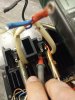
Here i see the emitter of upper transistor :
Last edited:
TupolevFan
Super Member
And further down is the mid point (output) between emitter resistors. So as i can conclude i can't access points between two resistors from the same side of the heatsink. ???
I do have mini grabbers.
I do have mini grabbers.
Yes, Tupolevfan is looking at the LOWER eyelets, where you can see that there is no connection, the upper eyelets have a soldered link wire visible on them.Have to use the eyelets from the upside.
TupolevFan
Super Member
Bingo John. I somehow with my mid aged eyes did not see that small wire at the other side of the heatsink and thought that those are not connected either but i should have tried Ohm meeter in between those. So I attach the mini grabbers to those Cool. I was already going to unscrew the heatsink to make sure. But it seems to me ( i do not see the wiring) that one eyelet is from emitter resistor of one pair and the other is from the other. But if those are all matched then it does not matter and voltage drop should be the same as they are all connected.Yes, Tupolevfan is looking at the LOWER eyelets, where you can see that there is no connection, the upper eyelets have a soldered link wire visible on them.
Thanks a Lot everybody for clarification at least when time comes i won't need to do additional research
TupolevFan
Super Member
Now I will describe the changes.
All black flag capacitors were replaced by ceramic G0G/NP0. 3pf caps(C23,C25,C24,C26,C53,C54,C55,C56) were replaced with SMD version 2% tolerance 200 V. 581-12102U3R0BAT2A
22pF C29,C30. replaced with Kemet 22pF 1% tolerance 250V G0G/NP0 80-C410C220FAG5TA
33pF C39,C40,C41,C42 replaced with Kemet 33pF 2% tolerance 200V G0G/NP0 80-C317C330G2G
Bypassing triple diodes D01,D02 capacitors C07, C08 and C13,C14 replaced with Wima film caps 4.7 x 50V because of that C09,C10 C15, C16 removed. installed Film capacitors in place of C09,10,15,16 as they fitted in there best. MKS2B044701K00KSC9 https://www.mouser.com/ProductDetail/WIMA/MKS2B044701K00KSC9?qs=dTJS0cRn7og/fq2MBN0Drw==
C61,C62 zener (ZD01,ZD02) shunting caps I used United Chemi-Con 100uF x 63V Hybrid Polymer capacitor 661-HHSD630L101MJC5S
Same for C17,C18 United Chemi-Con 100uF x 63V Hybrid Polymer capacitor 661-HHSD630L101MJC5S
C51, C52 in protection circuitry were actually 0.47uF (schematic calls for 1uF) replaced by Kemet 0.47 x 63 Film caps MMK5474K63J02L4BULK https://www.mouser.com/ProductDetail/KEMET/MMK5474K63J02L4BULK?qs=g8jvKo8sMA8goD6djiqiMg==
C01,C02,C03,C04 originally 470uF x 63 V replaced by 1000 uF x 80V 661-EGPD800E102ML35H
C19,C20,C45, C46 - those are not to be found on schematics and i followed the trend and replaced those originally 3.3 x 63 uF caps by 47 X 63 uF.
Those are additional power supply bypassing caps installed near the driver transistors. What i think might be better is installing 3.3 - 4.7 uF film cap here for example this one https://www.mouser.com/ProductDetail/WIMA/MKS2C044701M00JO00?qs=2G4irm/qADzRWalSjO2gXA==
Zener diodes ZD01,02 replaced with 78-BZX85B27-TAP
ZD03,04 replaced with 78-BZX55B13-TAP
Hopefully did not forget to mention anything important.
heatsink compound and mica films of driver transistors and output transistors replaced. On Otput transistors heat transfer compound was dry and flaky so this is important step in resto
All black flag capacitors were replaced by ceramic G0G/NP0. 3pf caps(C23,C25,C24,C26,C53,C54,C55,C56) were replaced with SMD version 2% tolerance 200 V. 581-12102U3R0BAT2A
22pF C29,C30. replaced with Kemet 22pF 1% tolerance 250V G0G/NP0 80-C410C220FAG5TA
33pF C39,C40,C41,C42 replaced with Kemet 33pF 2% tolerance 200V G0G/NP0 80-C317C330G2G
Bypassing triple diodes D01,D02 capacitors C07, C08 and C13,C14 replaced with Wima film caps 4.7 x 50V because of that C09,C10 C15, C16 removed. installed Film capacitors in place of C09,10,15,16 as they fitted in there best. MKS2B044701K00KSC9 https://www.mouser.com/ProductDetail/WIMA/MKS2B044701K00KSC9?qs=dTJS0cRn7og/fq2MBN0Drw==
C61,C62 zener (ZD01,ZD02) shunting caps I used United Chemi-Con 100uF x 63V Hybrid Polymer capacitor 661-HHSD630L101MJC5S
Same for C17,C18 United Chemi-Con 100uF x 63V Hybrid Polymer capacitor 661-HHSD630L101MJC5S
C51, C52 in protection circuitry were actually 0.47uF (schematic calls for 1uF) replaced by Kemet 0.47 x 63 Film caps MMK5474K63J02L4BULK https://www.mouser.com/ProductDetail/KEMET/MMK5474K63J02L4BULK?qs=g8jvKo8sMA8goD6djiqiMg==
C01,C02,C03,C04 originally 470uF x 63 V replaced by 1000 uF x 80V 661-EGPD800E102ML35H
C19,C20,C45, C46 - those are not to be found on schematics and i followed the trend and replaced those originally 3.3 x 63 uF caps by 47 X 63 uF.
Those are additional power supply bypassing caps installed near the driver transistors. What i think might be better is installing 3.3 - 4.7 uF film cap here for example this one https://www.mouser.com/ProductDetail/WIMA/MKS2C044701M00JO00?qs=2G4irm/qADzRWalSjO2gXA==
Zener diodes ZD01,02 replaced with 78-BZX85B27-TAP
ZD03,04 replaced with 78-BZX55B13-TAP
Hopefully did not forget to mention anything important.
heatsink compound and mica films of driver transistors and output transistors replaced. On Otput transistors heat transfer compound was dry and flaky so this is important step in resto
Last edited:

GrisPato
Super Member
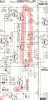
This is an interesting capacitor placement. They are on the schematic of the AU-819. And according to that schematic they are between positive and negative rail and not from each rail to ground. I am wondering what is the use of that.C19,C20,C45, C46 - those are not to be found on schematics and i followed the trend and replaced those originally 3.3 x 63 uF caps by 47 X 63 uF.
Those are additional power supply bypassing caps installed near the driver transistors
TupolevFan
Super Member
Actually i did not notice that. Usually such things(installing cap between negative and positive rails ) are done to reduce/eliminate differential interference and it is more applicable to switching mode dual polar power supply. So it looks like single film cap with non inductive construction would even make more sense than increasing the e-cap capacitance.This is an interesting capacitor placement. They are on the schematic of the AU-819. And according to that schematic they are between positive and negative rail and not from each rail to ground. I am wondering what is the use of that.
View attachment 2571855
Last edited:
TupolevFan
Super Member
I actually have this Nichicon(see picture) series and 3.3 and 3.3 in series is 1.65 uF i have 1.5 uF x 250 V (on the picture 1.uF) PP capacitor. Those are non inductive. Can remove black wire and instead connect those two points with the cap (probably install it from the foil side. and instead of C19,C20, C45, C46 install jumpers. bum and got rid of 4 e-caps.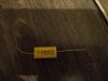

I had the same issue with the one I just worked on. One end the eyelet was wired, the other end doesn't appear to be. So on that end I reached in with the mini grabber and clipped onto the lead of the emitter resistor. I measured about .7-.8Ω, which sounds about right for 2 .33Ω resistors and the associated meter lead resistance.Bingo John. I somehow with my mid aged eyes did not see that small wire at the other side of the heatsink and thought that those are not connected either but i should have tried Ohm meeter in between those. So I attach the mini grabbers to those Cool. I was already going to unscrew the heatsink to make sure. But it seems to me ( i do not see the wiring) that one eyelet is from emitter resistor of one pair and the other is from the other. But if those are all matched then it does not matter and voltage drop should be the same as they are all connected.
Thanks a Lot everybody for clarification at least when time comes i won't need to do additional research
TupolevFan
Super Member
My regular multimeter reads around .8 to .95 ohm between those 2 eyelets. Good to see you here on the thread Ray.I had the same issue with the one I just worked on. One end the eyelet was wired, the other end doesn't appear to be. So on that end I reached in with the mini grabber and clipped onto the lead of the emitter resistor. I measured about .7-.8Ω, which sounds about right for 2 .33Ω resistors and the associated meter lead resistance.
To be fair, the 717 you bought may have worked before it was shipped. I know some carriers take the "drop" in drop ship literally, considering the condition of some boxes I've received.I bought a "working" AU717 on ebay, paid $480. It shows up, and plug into the dim bulb. Comes out of protection but no sound. It looked all original, but very dirty inside. Contacted the seller, and he was willing to full refund but I would eat the return shipping. I made a lower offer and we came to a fair deal, ebay refunded some monies and the sales tax. It did piss me off that he lied about it working, but I had plans to rebuild it before bidding. Funny how every fusible was open.. damn liers. Ebay is pretty good about buyers getting items not working so you have that in your favor.
Good luck finding a repair center, here in central NJ there are none. There is a repair shop down near Trenton, but he has no interest in doing full recaps.
Thanks TupolevFan. Late as usual.My regular multimeter reads around .8 to .95 ohm between those 2 eyelets. Good to see you here on the thread Ray.
TupolevFan
Super Member
I will soon continue my descriptions as I went through all the boards but did not have time to post here.
However I do have a question related to oval capacitors (main filter caps). I opened them up and gutted all of them. My question is what do you people use in order to cleanly and completely remove all the remains from inside walls. I removed all the stuff but thin layer of sticky "something" remains here and there and more importantly smells. How did you get rid of the those remains and again which is more important how did you get rid of the odor.
Thanks,
Deniss
However I do have a question related to oval capacitors (main filter caps). I opened them up and gutted all of them. My question is what do you people use in order to cleanly and completely remove all the remains from inside walls. I removed all the stuff but thin layer of sticky "something" remains here and there and more importantly smells. How did you get rid of the those remains and again which is more important how did you get rid of the odor.
Thanks,
Deniss
I can't remember what I used, maybe a squirt of flux cleaner followed by rinsing in warm water with some dish soap (Fairy Liquid), I don't remember anything that's in there being difficult to remove - once they are gutted.How did you get rid of the those remains and again which is more important how did you get rid of the odor.
TupolevFan
Super Member
Yes i may be phrased it a bit incorrect. I meant effectivelyI can't remember what I used, maybe a squirt of flux cleaner followed by rinsing in warm water with some dish soap (Fairy Liquid), I don't remember anything that's in there being difficult to remove - once they are gutted.
))