• The move to the new server is done. There are some software and database maintenance updates in process. This has us passing the hat around to help out. We appreciate any donations. Seriously, even a dollar helps. The payment page may be found here - https://www.audiokarma.org/support.html

Sansui AU-919 Black Flag Capacitors, Some help please

Thanks,
Yes those 3pF fitted well. I also went with those because of their Voltage rating and tolerance
Yes, that is interesting to. For my AU-D907 Limited I need 1pF, which I bought, they have a tolerance of 0.25pF ( so tolerance of 25%).In SMD they go down to 0.01pF ( would have to buy a 100.000) and 0.1pF.
Question of course is if this matters?
Did Sansui use the polystyrene capacitors (in the AU-819/919/X1) instead of ceramics in this location because of better tolerance? In the AU-519/719 they used standard ceramics and they use the same fast design or maybe less pushed to the limit.
 
Yes, that is interesting to. For my AU-D907 Limited I need 1pF, which I bought, they have a tolerance of 0.25pF ( so tolerance of 25%).In SMD they go down to 0.01pF ( would have to buy a 100.000) and 0.1pF.
Question of course is if this matters?
Did Sansui use the polystyrene capacitors (in the AU-819/919/X1) instead of ceramics in this location because of better tolerance? In the AU-519/719 they used standard ceramics and they use the same fast design or maybe less pushed to the limit.

Yes that is a good question. However knowing that those units have some instability issues i would rather go with more precision in tolerance .
Here is exact part i used 12102U3R0BAT2A. Keep in mind that those SMD components have different packages which translates into different sizes. I used the one which was 3.2 mm. Here is exact part i used for 3pF: 12102U3R0BAT2A https://www.mouser.com/ProductDetail/kyocera-avx/12102u3r0bat2a/?qs=p3V6xRurDKkGoGQQ/KP61A==&countrycode=US&currencycode=USD. One could use 2.8mm as well i guess
 
Last edited:
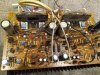
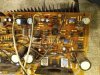
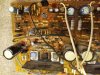
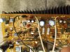
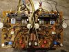
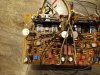
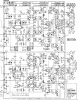
Differential amplifier. dual FET 2SK129 (FET01 and FET02 for the other channel) + TR01 (TR02 for the other channel) , TR03(TR04 for the other channel) form Cascode differential amplifier which is common source - common base(at least it looks to me ) . TR01(TR02) and TR03(TR04) are infamous 2SC1313. I was debating with myself what to use to replace those and came to the conclusion that BC550C is a good candidate. Glancing at current source on transistor TR05(TR06) we can estimate constant current it producing. It is basically the current through R15 (R16). From one side of R16 is 40V and the other it shows around 33 (which is a bit strange to me as Zener ZD03/04 is 6.2V) We can calculate: (40 - 33) / 1k = 7mA. So 7 to 8 ma . this current is shared equally by each brunch of differential amp.
So TR01(02). and TR03(04) each biased at 3-4 ma. For BC550C there was a graph which shows the dependency of Ft from collector current. and for 3-4 ma Ft is around 200 - 230 Mhz. That is why i went with BC550C.

EDIT: after bellow discussion and some additional consideration (see below) BC550C were replaced with KSC1845F (have good batch from Newark where most HFEs are over 400).

Couple of words about ZD01(02). I went with the trend and replaced it with Vishay BZX55B9V1-TAP https://www.mouser.com/ProductDetail/vishay/bzx55b9v1-tap/?qs=yIvl1B2wDi7HjA/ATm0XbQ==&countrycode=US&currencycode=USD
However I question if this is necessary because it looks to me that this zener there for protection and in normal operation is NOT conducting thus has no influence on anything. Zener diodes usually noisy only when they are conducting.

C07/08 is what makes TR01,TR02,TR03,TR04 Common base in this differential stage and if you want to slightly increase the value of this capacitor then i do not think there will be any harm in it. I went with the stock value and used:
661-EKY350ELL221MJC
Also replaced C05/C06 with PP film caps of the same value as stock.

ZD03/ZD04 replaced with
78-BZX55B6V2-TAP
C13 and C14 i used Hybrid polymer by United Chemi-Con:
661-HHSD630L101MJC5S

C23,C24,C25,C26 Originally 100uF x 50V replaced with 330uF X 63 V
661-ELXY630ELL271MK
all bypassing film caps(C27,C28,C29,C30) were dipped into sansui glue. I replaced those with 0.33uF X 100 V film caps ( i think i used Kemet).
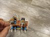
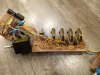
each pair of C19, C21. and C20,C22 were replaced by three Rubycon MU 15uF x 25V connected in parallel on custom made adapter. Did not use 22uF as those are rated only 16V
C17, C18 removed as those Rubycon MU are film caps.

VR01/VR02 trimmers replaced with 652-3386X-1-471LF

Resistors R43,R44,R45,R46 replaced with RN65 series.

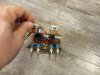
Black flag caps C35,36,37,38 3pF replaced by G0G 3P x 200V 581-12102U3R0BAT2A
Black flag caps C01,02 33pF replaced with Kemet G0G 33pF X 200 2% 80-C317C330G2G

There was some glue on this particular board and it was removed

 
Last edited:
I did read your post considering the options for replacement of the 2sc1313 and was surprised why you didn't go with the 2sc1845 as they use them in the same position in the AU-X1 and CA-F1, although the surrounding circuit is a little different. ( And I don't know enough to decide if that matters or not).
I always got the feeling Sansui used there remaining stock of the 2sc1313/ 2sa726 where appropriate during the change to 2sa992/2sc1845 and the latest are most of the time adequate replacements.
 
I did read your post considering the options for replacement of the 2sc1313 and was surprised why you didn't go with the 2sc1845 as they use them in the same position in the AU-X1 and CA-F1, although the surrounding circuit is a little different. ( And I don't know enough to decide if that matters or not).
I always got the feeling Sansui used there remaining stock of the 2sc1313/ 2sa726 where appropriate during the change to 2sa992/2sc1845 and the latest are most of the time adequate replacements.
Hmm you actually made me think. As i did not look at the ksc1845 graphs of Ft from Ic and it looks like it should perform similar as graph shows that Ft rises to 200 Mhz at 3-4 mA and no worries about collector emitter voltage. I will probably re-think this.


EDIT: OK You made me change my mind. I replaced BC with KSC1845FTA and i got very good batch of those from Newark with most HFEs over 400. :)))
 
Last edited:
I somehow was under the impression that KSC1845 Ft at 1ma was it's peak and usually this cascode configuration is used in low voltage components and/or to increase bandwidth. and for 2SC1313 FT is 200Mhz so it seemed to me that BC550 was closer match in this case but now looking at the graph for 1845 i see that it is around 200Mhz for Ic 3.5 ma. So i think KSC1845 also good choice. Thanks for pointing that out to me.
 
Last edited:
You did all the work in verifying. I simply look at what Sansui uses if there is a comparison because I don't have the knowledge ( yet ) to really compare specifications. I learn little by little from people like you. So this was ina way a lucky guess from my side.
At least you don't have to bend the leads ;)
 
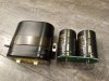
On a separate note i finally got capacitors for main filter caps as Mouser did not have them in stock for a while. they are 15 + USD each and we need 8 for this amp. Here is the one i will use :
https://www.mouser.com/ProductDetail/KEMET/ALC70A103EH100?qs=PqoDHHvF648hVPxK1TXGNQ==
Those are 10000uF rated at 100V. Dimension are : Diameter 40mm and height 60mm. those are 18000 Hours @ 85C . Ripple Current @ 100Hz at 85 C is 8.7 and at 10kHz 10.35A. Max ESR @100Hz is 34mOhm

I ordered 4 peaces of the same capacitors @ Mouser back in February and paid 11.8 USD per each. (they were backordered at that time). I will use them in my personal Accuphase E-202. Mouser decided to bump up the price as you can see. This caps are Kemet's new line.
 
Last edited:
On F2842 F2843 and F2846 all Mylar film caps were replaced by PP film caps of the same value and tolerance (or better tolerance) by Kemet, Wima and Panasonic.
Toggle switches on F2846 were desoldered, disassembled, manually cleaned, lubed, reassembled and soldered back to the board.
 
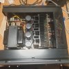
Question to guru: I somehow vaguely understand (from Service Manual ) where am i supposed to measure the idle current as emitter resistors are inside the heatsink assembly and it is a bit annoying. Sure I can disassemble the heatsink and take a look but if i could avoid it would be nice as it is not obvious and buried under the heatsink assembly. Does anybody have a picture where exactly to attach the probes?
Edit : well i will need to attach to emitters of transistor's themselves. Very inconvenient.
 
Last edited:
Question to guru: I somehow vaguely understand (from Service Manual ) where am i supposed to measure the idle current as emitter resistors are inside the heatsink assembly and it is a bit annoying. Sure I can disassemble the heatsink and take a look but if i could avoid it would be nice as it is not obvious and buried under the heatsink assembly. Does anybody have a picture where exactly to attach the probes?
Edit : well i will need to attach to emitters of transistor's themselves. Very inconvenient.
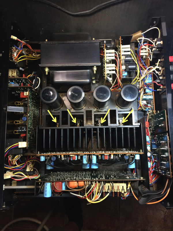
As far as I know ( this is true for the AU-819 ) you can use the eyelets on the adapters to measure the bias current.

20220208_001417.jpg

You can see them in this picture.
 
I think these are the eyelets....
Yes, a lot better picture. Although batter looking at the service manual of the AU-919 it looks like they want the eyelet next to it ( from the emitter pin?) but I am not sure, it's really difficult to see.
 
Back
Top Bottom