


You are using an out of date browser. It may not display this or other websites correctly.
You should upgrade or use an alternative browser.
You should upgrade or use an alternative browser.
Sansui AU-919 Black Flag Capacitors, Some help please
- Thread starter sjackh
- Start date
TupolevFan
Super Member
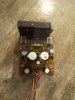
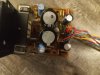
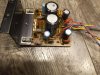
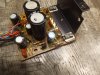 Here are before picture of regulated power supply :
TupolevFan
Super Member
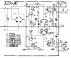
List of replacements for F-2844 (Regulated power supply)
TR01 2SD357 replaced with MJE15030G
TR03 2SB527 replaced with MJE15031G
TR02 2SC1313 replaced with ZTX696
TR04 2SC726 replaced with ZTX796
ZD01 Zener diode 24V replaced with Vishay TZX24C-TR 2% Low noise zener.
C01, C01 1000uF 63V replaced with Rubycon MXG series 63MXG3300MEFCSN22X35 CAP ALUM 3300UF 20% 63V SNAP IN : WARNING due to thick leads I had to gently enlarge the original holes
C11,C12 Originally 100uF x 50V upgraded to 270uF x 63V UPJ1J271MHD1TO
C07,C08 originally 100uF 35 V to 120uF x 50 V UPW1H121MPD6
C06 zenner shunting diode originally 100uF x 25V upgraded to Hybrid polymer 100uF x 63 V HHSC630ELL101MJC5S
R07 zener feeding resistor replaced with Vishay low TKE wire wound of the same value
As with F-2845 RB-152 replacement is not yet ready but will use Vishay BYW36-TR
Will test the board as soon as replacement adapter for RB152 arrives.
TR01 2SD357 replaced with MJE15030G
TR03 2SB527 replaced with MJE15031G
TR02 2SC1313 replaced with ZTX696
TR04 2SC726 replaced with ZTX796
ZD01 Zener diode 24V replaced with Vishay TZX24C-TR 2% Low noise zener.
C01, C01 1000uF 63V replaced with Rubycon MXG series 63MXG3300MEFCSN22X35 CAP ALUM 3300UF 20% 63V SNAP IN : WARNING due to thick leads I had to gently enlarge the original holes
C11,C12 Originally 100uF x 50V upgraded to 270uF x 63V UPJ1J271MHD1TO
C07,C08 originally 100uF 35 V to 120uF x 50 V UPW1H121MPD6
C06 zenner shunting diode originally 100uF x 25V upgraded to Hybrid polymer 100uF x 63 V HHSC630ELL101MJC5S
R07 zener feeding resistor replaced with Vishay low TKE wire wound of the same value
As with F-2845 RB-152 replacement is not yet ready but will use Vishay BYW36-TR
Will test the board as soon as replacement adapter for RB152 arrives.
Last edited:
TupolevFan
Super Member
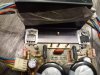
 Here are pictures of updated F2844 without RB152.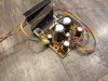

MIJ_Pioneer
Super Member
This board (F-2845)practically contains main filter's rectification diodes and capacitance multipliers which feed driver's board input differential stages, diamond differential VAS stages and pre-driver stages. As Leestereo pointed out this would benefit from increased capacitance. Now it is worth pointing out that non of those transistor stages on F2845 are Voltage regulators those just ripple eliminator stages or call it active RC filters. Besides installing higher capacitance this should also benefit from replacing the TR01, TR02, TR03,TR04 with high hfe transistors like Darlington because as the name suggests it multiplies the capacitance installed at their bases. The formula is C *(hfe +1). Other words if the hfe of the transistor is 100 and you installed 100uF at it's base, this 100uF becomes 10000uF. However due to higher Voltage drop on base emitter junction for Darlington transistors output Voltage might be around 1 Volts less then with originals and if you are picky about it then you will need to manipulate a bit with the resistive voltage divider at the base of the transistor. For example for TR01 the output voltage is determined by R05,R07. So if you were going to install darlington instead of TR01 and voltage slightly dropped then lowering slightly value of R05 should bling the Voltage back.
However even more important to to notice here that Voltage drop here is around 16 -20 Volts (not sure about the current) but i bet it does dissipate some power so i for reliability would use more robust transistors.
I had couple of Darlington BDX33C/BDX34C TO-220 transistors which have min hfe 750
now I swapped
TR03, TR04 2SB527 to BDX34C
TR01,TR02 2SD357 to BDX33C
Additional plus is that BDX33/34 have internal protection diode between collector and emitter which is good to have in this circuit.
C11,C12,C13,C14 on schematic 100uF x63 but on board was 220uf x 63 were replaced with United Chemi-Con 470 uF x 80V KYB series capacitors 16mm in diameter. EKYB800ELL471ML20S
C7,C8,C9,C10 originally 220uF x 80V,C15,C16,C1,C18 originally 220uF x 63 V were all replaced with United Chemi-Con 820 uF x 80V KYB series capacitors 16mm in diameter. the hight is identical (may be 1 - 2mm taller) to originals. EKYB800ELL821MLN3S
I also have replaced all 10 Ohm CC Resistors as some of them were peeling. Replaced with Vishay CMF65 series 10 Ohm.
I did not yet install replacements for RB152 bridge rectifiers as i am waiting on adapter board for that to arrive.
as a diode selection to replace RB152 i will use Vishay BYW36-TR
Very impressive and we'll detailed. AK is lucky to have you!
I used MJE15030G/MJE15031G for TR01-04. Given your findings, how do you think they will fair in this position? I noticed you used the MJE in the regulated PS but not here.

GrisPato
Super Member
Nice to see you work!
Interesting for me, just learned the difference between capacitance multiplier and regulated power supply and there you come with some explanation.
I was just wondering what are the disadvantages of using the Darlington to increase the multiplication except the extra be voltage drop?
Just because most of the time each advantage comes with its own disadvantages.
And now I have to read more about this, why it works like this, more capacitance because of the gain of a transistor
This board (F-2845)practically contains main filter's rectification diodes and capacitance multipliers which feed driver's board input differential stages, diamond differential VAS stages and pre-driver stages.
Interesting for me, just learned the difference between capacitance multiplier and regulated power supply and there you come with some explanation.
I was just wondering what are the disadvantages of using the Darlington to increase the multiplication except the extra be voltage drop?
Just because most of the time each advantage comes with its own disadvantages.
And now I have to read more about this, why it works like this, more capacitance because of the gain of a transistor

TupolevFan
Super Member
Good point and thanks to @Leestereo warning i did not miss this nuanse and installed them correctly. Thanks for pointing that out.I was checking you had C07 & C08 in the right way round.
TupolevFan
Super Member
Nah i am lucky to have this community. I am not that good at mechanical work and F-2845 heard a lot of cursing from me when i was installing those screw terminalsNice to see you work!
Interesting for me, just learned the difference between capacitance multiplier and regulated power supply and there you come with some explanation.
I was just wondering what are the disadvantages of using the Darlington to increase the multiplication except the extra be voltage drop?
Just because most of the time each advantage comes with its own disadvantages.
And now I have to read more about this, why it works like this, more capacitance because of the gain of a transistor
 )))
)))Regarding your MJE transistors i think they will do better than original in terms of robustness and on par in terms of electrical performance as their actual hfe ussually around 100 - 120 For NPN and in 180 to 220 for PNP. So no worries here. Also because they are not darlingtons output Voltage will not be 0.7 Volts lower. Of cause 0.7 Volts is nothing when expected output is 50+ volts, but if you have bipolar disorder which i somtemes exibit ))))))) (kidding)......
TupolevFan
Super Member
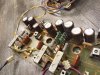
My RB-152 adapter boards have arrived here are 2844 and 2845 boards with installed rectifiers 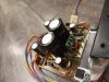
TupolevFan
Super Member
I ordered there one more board and i think you can guess what it would be for 
TupolevFan
Super Member
For main filter caps I plan to use this KEMET caps from ALC70A series. https://www.mouser.com/ProductDetail/KEMET/ALC70A103EH100?qs=PqoDHHvF648hVPxK1TXGNQ==&countrycode=US¤cycode=USD
Those are 10000uF x 100V. 40mm in diameter and 62mm tall. Nice ESR and ripple numbers
Those are 10000uF x 100V. 40mm in diameter and 62mm tall. Nice ESR and ripple numbers
Last edited:
TupolevFan
Super Member
Question to a Community regarding black flag caps. I plan to replace them with NP0/C0G ceramic caps. I can't seem to find tolerance for those caps in SM. It says they are rated for 125V.
So i can get for example 3pf. +- 0.5pF x 250V (which is roughly within 20% tolerance). or i could get 100V(which should be enough but will be derated comparing to original) version and tolerance +- 0.1pF ( 3-4 %) so what are you usually using ? I always used Kemet but can't get them now in more precise version. Of cause i can adapt smd version and there you could find very precise versions and sufficient Voltage.
Thanks everybody
So i can get for example 3pf. +- 0.5pF x 250V (which is roughly within 20% tolerance). or i could get 100V(which should be enough but will be derated comparing to original) version and tolerance +- 0.1pF ( 3-4 %) so what are you usually using ? I always used Kemet but can't get them now in more precise version. Of cause i can adapt smd version and there you could find very precise versions and sufficient Voltage.
Thanks everybody

I've always used TDK 100V rated caps. FG series, drop right in, here's one for example: FG28C0G2A220JNT06 TDK | MouserQuestion to a Community regarding black flag caps. I plan to replace them with NP0/C0G ceramic caps. I can't seem to find tolerance for those caps in SM. It says they are rated for 125V.
So i can get for example 3pf. +- 0.5pF x 250V (which is roughly within 20% tolerance). or i could get 100V(which should be enough but will be derated comparing to original) version and tolerance +- 0.1pF ( 3-4 %) so what are you usually using ? I always used Kemet but can't get them now in more precise version. Of cause i can adapt smd version and there you could find very precise versions and sufficient Voltage.
Thanks everybody
TupolevFan
Super Member
Flat amplifier F-2841
I am debating what to use as a replacement for 2SC1313 in differential amplifier (TR01,TR03 and TR02, TR04).
I have the following to choose from : ZTX694 - nice transistor but what worries me is that ft is taken @50ma and there is no curve in datasheet to show dependency of Ft from collector current. And usually the curve is like bell with peak @some Ic. I wonder what it would be @aprox 4ma which is our case and suspect it would be way bellow 100Mhz.
Next transistor is MPSA18 by Central semiconductor. Max Vce = 45V ft Typ = 160Mhz @Ic=1ma
Next one is BC550C I think i have Onsemi version. Max Vce = 45V ftTyp = 300Mhz @Ic=1ma
I also have around 30 NOS Toshiba 2SC3112. Max Vce = 50V ftTyp = 250Mhz @Ic = 1ma
Would appreciate your input.
I am debating what to use as a replacement for 2SC1313 in differential amplifier (TR01,TR03 and TR02, TR04).
I have the following to choose from : ZTX694 - nice transistor but what worries me is that ft is taken @50ma and there is no curve in datasheet to show dependency of Ft from collector current. And usually the curve is like bell with peak @some Ic. I wonder what it would be @aprox 4ma which is our case and suspect it would be way bellow 100Mhz.
Next transistor is MPSA18 by Central semiconductor. Max Vce = 45V ft Typ = 160Mhz @Ic=1ma
Next one is BC550C I think i have Onsemi version. Max Vce = 45V ftTyp = 300Mhz @Ic=1ma
I also have around 30 NOS Toshiba 2SC3112. Max Vce = 50V ftTyp = 250Mhz @Ic = 1ma
Would appreciate your input.
Last edited:

TupolevFan
Super Member
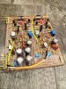
Ok it has been a while since i posted and since then I rebuild Flat/control amp, and Drivers Board (Power Amp).
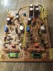
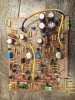
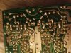
I again again forgot take before pictures for Flat amp. Now i will post pics of Flat amp (F-2841)with newly installed components but will describe what was done later as i have to go somewhere.
I used Rubycon MU capacitors here but not satisfied by components alignment on my adapter, however decided to stress heat components to re-align slightly crooked MU caps. So do not judge too hard.
Also as you will see on pics for 3pF black flags I decided to go with G0G/NP0 SMD ceramic caps as they were 200V and +-0.1pF tolerance (which is about 2 - 3%)
I again again forgot take before pictures for Flat amp. Now i will post pics of Flat amp (F-2841)with newly installed components but will describe what was done later as i have to go somewhere.
I used Rubycon MU capacitors here but not satisfied by components alignment on my adapter, however decided to stress heat components to re-align slightly crooked MU caps. So do not judge too hard.
Also as you will see on pics for 3pF black flags I decided to go with G0G/NP0 SMD ceramic caps as they were 200V and +-0.1pF tolerance (which is about 2 - 3%)
TupolevFan
Super Member
EDIT: WARNING ZD01 on this pictures installed backwards by mistake!!!!!!
Last edited:
TupolevFan
Super Member
Thanks,Nice work. Interesting use of SMD capacitors. Especially the pF ones on the trace side, they fit well between the solderpads!
Yes those 3pF fitted well. I also went with those because of their Voltage rating and tolerance