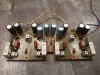
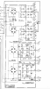
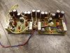
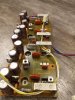
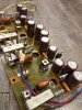
This board (F-2845)practically contains main filter's rectification diodes and capacitance multipliers which feed driver's board input differential stages, diamond differential VAS stages and pre-driver stages. As Leestereo pointed out this would benefit from increased capacitance. Now it is worth pointing out that non of those transistor stages on F2845 are Voltage regulators those just ripple eliminator stages or call it active RC filters. Besides installing higher capacitance this should also benefit from replacing the TR01, TR02, TR03,TR04 with high hfe transistors like Darlington because as the name suggests it multiplies the capacitance installed at their bases. The formula is C *(hfe +1). Other words if the hfe of the transistor is 100 and you installed 100uF at it's base, this 100uF becomes 10000uF. However due to higher Voltage drop on base emitter junction for Darlington transistors output Voltage might be around 1 Volts less then with originals and if you are picky about it then you will need to manipulate a bit with the resistive voltage divider at the base of the transistor. For example for TR01 the output voltage is determined by R05,R07. So if you were going to install darlington instead of TR01 and voltage slightly dropped then lowering slightly value of R05 should bring the Voltage back.
However even more important to to notice here that Voltage drop here is around 16 -20 Volts (not sure about the current) but i bet it does dissipate some power so i for reliability would use more robust transistors.
I had couple of Darlington BDX33C/BDX34C TO-220 transistors which have min hfe 750
now I swapped
TR03, TR04 2SB527 to BDX34C
TR01,TR02 2SD357 to BDX33C
Additional plus is that BDX33/34 have internal protection diode between collector and emitter which is good to have in this circuit.
C11,C12,C13,C14 on schematic 100uF x63 but on board was 220uf x 63 were replaced with United Chemi-Con 470 uF x 80V KYB series capacitors 16mm in diameter. EKYB800ELL471ML20S
C7,C8,C9,C10 originally 220uF x 80V,C15,C16,C1,C18 originally 220uF x 63 V were all replaced with United Chemi-Con 820 uF x 80V KYB series capacitors 16mm in diameter. the hight is identical (may be 1 - 2mm taller) to originals. EKYB800ELL821MLN3S
I also have replaced all 10 Ohm CC Resistors as some of them were peeling. Replaced with Vishay CMF65 series 10 Ohm.
I did not yet install replacements for RB152 bridge rectifiers as i am waiting on adapter board for that to arrive.
as a diode selection to replace RB152 i will use Vishay BYW36-TR



 ))
))