• Please note that Audiokarma will be offline briefly for updates early on Monday morning, September 28th.

Sansui Au919 Parts

Thanks for the description of your amp! I'm glad another Sansui is back from the dead. Since I also have one of these amps and I love it, I'm curious if Mr. Echowars will reveal if and how he improved the design of the amp, in addition to undoing all the crappy tech work of the amp's past. Reading about those mods EW did to the Kenwood Supreme amp a while back was very interesting especially since those amps are so highly regarded in stock condition, somewhat like the 919. If you are willing to disclose this information I know we will all appreciate these as pearls of wisdom. Thanks!!

Collin
 
noveltone:

Don't want to take words out of EW's mouth, but my sense is that he would say that the improvement in the amp comes not from modifying the amp per se (design modifications and the like) as much as it is from simply using better components than the stock unit had (with the exception of the OnSemi's, that is...).

Glenn?
 
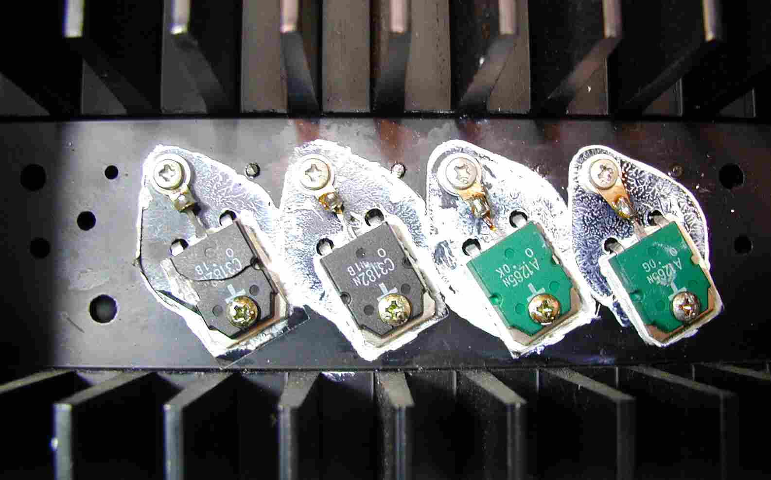
I found this image on amp8.com for an AUX-11. Obviously someone has replaced the original TO-3 transistors with flat-packs. I thought there were 3 pairs of transistors in an AU-X1 maybe thats why one has cooked itself ??

http://amp8.com/sansui/x-xx/x11/au-x11.htm

au-x11-1.jpg
 
...Since I also have one of these amps and I love it, I'm curious if Mr. Echowars will reveal if and how he improved the design of the amp, in addition to undoing all the crappy tech work of the amp's past.
I did NOT set out to improve Sansui's design...the amp doesn't need my help. What I tried to do was to restore the amp to the point it was when it was new by replacing weak transistors, out-of-tolerace resistors, all the old electrolytic caps, the bad pf caps that cause oscillation, and the crappy stock trimpots. The only real modification from stock is the redesign of the power connections to the power supply board: http://www.audiokarma.org/forums/showthread.php?t=123539

I found this image on amp8.com for an AUX-11.
More or less what I wanted to do with the 919, but the transistor sockets would not allow this.
 
Thanks for your comments on what you did do to the amp, EW. I have one question, however. Although some time ago a gentleman looked at my AU-919 and determined that the work I did was not causing it to oscillate, I wonder now what you mean by "bad pf caps that cause oscillation." Are those small value (picofarad) caps such as the styrene caps on the driver board? If an amp is oscillating, I get the sense that it's bad news and that you could hear it. Is that true? Thanks for your thoughts.


Also, interesting pic of the to-3 modification. I still hope to sink a few hours in to figuring a way to make the toshibas work....someday....

Collin
 
The 919 uses the same crappy pf caps that the Kenwood L-07MII used. These are what I call 'Black Flag' caps ('cause that's kinda what they look like), and seem to be an early multilayer ceramic design. They do not hold their value, and seem to be easily damaged. I replaced ALL of them in the 919 with silver mica caps (they are used in both the amp and preamp).

I'm not aware of any issues with the polystyrene caps...
 
The 919 uses the same crappy pf caps that the Kenwood L-07MII used. These are what I call 'Black Flag' caps ('cause that's kinda what they look like), and seem to be an early multilayer ceramic design. They do not hold their value, and seem to be easily damaged. I replaced ALL of them in the 919 with silver mica caps (they are used in both the amp and preamp).

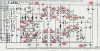
I'm finally getting to this project now. From what's in my amp, I need 3 pf, 9 pf and 22 pf, 125V silver mica caps. I can find everything except the 9 pf in a radial lead format. What do you all think is the best alternative to this cap, a 10 pf/500V silver mica or a 9.1 pf/100V monolithic ceramic cap? Please see attached image of this board. It's toward the right side. Edit: It's C24.

Many thanks!

Collin
 

Attachments

  • AU919  eq.jpg
    AU919 eq.jpg
    101.5 KB · Views: 84
It's fine to do the preamp, but the amp is where the work needs to get done. What's more, if I was expecting any kind of sonic improvement, I'd do everything I could to use ALL silver-mica caps...and NO ceramic caps. If you can't find a 9pf, a 10pf will be fine.
 
Ok I'll use the 10 pf silver-mica cap in place of the 9 pf. Thanks for your reply, EW. For others looking I was able to find these caps at the following website (no affiliation, of course): http://www.justradios.com/mica.html. They have a few more values than parts connexion. I'll let you all know the news when it's finished.

Collin
 
So did you finish, Collin?

I am going back in to an AU-919 I recapped last year to replace all these 'black flag's as well as any parts touched by the corrosive glue (which appears to be quite a few). I wasn't aware of the potential issues with black flags and glue back when I recapped it.
 
X,

Wow a blast from the past. Thanks for asking about this project. I did recently and finally replace the "black flag" caps with silver micas. I am told these are for transistor stability more than sound shaping. I did not hear a difference in sound or anything, but I am glad for the opportunity to shore up this great amp, squeezing some more life out it.

Also, my DMM doesn't measure that low in capacitance, so I could not easily test whether the black flags were in my case out off-value. Any idea why some of these are elevated off the board and some aren't?

You know, one thing I did also was to replace the coupling caps in the flat amp with blackgates. These are the four caps whose positive leads are back-to-back in pairs, C19,20,21,22. I rarely use the flat amp, instead bypassing it with the JUMP switch, but I could really tell that the higher quality cap helped the mid-bass sound less tubby, more like the rest of the amp....clean Sansui sound. So, if you're in there, you might consider ordering some of these and replacing them.

Please do let us know how it turns out.....:yes:

Collin
 
X,

Wow a blast from the past. Thanks for asking about this project. I did recently and finally replace the "black flag" caps with silver micas. I am told these are for transistor stability more than sound shaping. I did not hear a difference in sound or anything, but I am glad for the opportunity to shore up this great amp, squeezing some more life out it.

Also, my DMM doesn't measure that low in capacitance, so I could not easily test whether the black flags were in my case out off-value. Any idea why some of these are elevated off the board and some aren't?

You know, one thing I did also was to replace the coupling caps in the flat amp with blackgates. These are the four caps whose positive leads are back-to-back in pairs, C19,20,21,22. I rarely use the flat amp, instead bypassing it with the JUMP switch, but I could really tell that the higher quality cap helped the mid-bass sound less tubby, more like the rest of the amp....clean Sansui sound. So, if you're in there, you might consider ordering some of these and replacing them.

Please do let us know how it turns out.....:yes:

Collin

Thanks for that extra info. I need to source the silver micas myself. Right now for those coupling caps I have Panasonic FC but I may upgrade them to Nichicon Fine Gold or Elna SilmicII just to see if I notice a difference. I don't have any Black Gate on hand.

I plan to use my Dremel to remove the corrosive glue and I hope to make a list of all effected parts as well for replacement. It's a bit more work than I expected to do - I wish I knew about this when I had it all pulled apart for recapping.

I may also replace the VRs with Bournes 25-turn pots for good measure!

I will keep you posted how it works out. Right now the amp is half torn down on the bench. I am going to start with an internal cleaning since its been uncovered in the rack since recapping.
 
Did F-2846 and F-2841 (Flat Amp) tonight, replacing trimpots with new 500 Ohm Bournes 25-turn sealed trimpots, replacing mylar caps with polypropylene caps, replacing 'black flag' caps with silver mica.

I then touched up every solder joint on both boards.

About a year ago I had already replaced the electrolytics with Panasonic FC and deoxited the switches and pots so they are good to go!

Next up is turn over and tone control boards. Then the "front" of the unit will be done and I can focus on the driver boards and equalizer amp boards. Then protection and power supply and I'll be all done!
 
Good work! Have you listened to the amp yet, with the partially completed changes? That amp will hopefully be good to go for another 20 years. Do you plan to replace the large oval caps? I am personally avoiding it since I don't have the time to do it right at the moment, but was wondering your thoughts on the matter.

Collin
 
Good work! Have you listened to the amp yet, with the partially completed changes? That amp will hopefully be good to go for another 20 years. Do you plan to replace the large oval caps? I am personally avoiding it since I don't have the time to do it right at the moment, but was wondering your thoughts on the matter.

Collin

I have not listened to it yet. It is still torn apart on my bench. I am taking my time in hopes to do it right this time. Last time I just went through and replaced the electrolytics and I regret not doing these other preventative maintenance/upgrade things then.

Last night I replaced the trimpots, mylars, and black flags on the EQ amp and the other two front-panel PCBs. Then I replaced the four signal path electrolytics on the connected/separated PCB with Elna Silmic II.

I do not plan to replace the oval caps just yet - for something of that magnitude I don't mind waiting until it's necessary. I like the ol' "stuff new caps in the old oval" trick but I hesitate to try it out on my only AU-919. If I find a parts unit down the road I would like to use it for practice.

I ran out of parts yesterday so the project is on hold pending a shipment from Digikey. When that arrives I should be able to finish the driver board before moving on to the power supply boards. They have the corrosive glue all over them and several parts are affected so I will probably not be able to button her back up and listen for a week or two because of the holidays.

I will report back once I make more progress!
 
Then I replaced the four signal path electrolytics on the connected/separated PCB with Elna Silmic II.

Xoaphexox,

There are also four signal path electrolytics on the Flat amp as well: c19, c20, c21, c22. The ones on the conn/sep board are only engaged if you put that switch in the "cap connected" mode, so you could set it to "direct connected" and be able to move those caps to the Flat Amp board. I'm just saying this because perhaps its more likely that you'll use the Flat amp, where those caps are in the signal path, than it is for you to need to use the "cap connected" setting, putting an additional four electrolytics in the signal path. Maybe you already got these, but just in case....

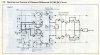
Also, in looking at the service manual showing the signal path through the Driver board, it looks to me as though C33, C34 (shown as 1 uF, 50V) are also in the signal path. See the attachment. So if I'm reading this correctly, and you had a mind to, you could replace this fella also while you're under the hood. I didn't do this last one, unfortunately, but will next time I"m in there.

Thanks for the update! Good luck when you get your Digikey shipment.

Collin
 

Attachments

  • Driver Signal.jpg
    Driver Signal.jpg
    67.5 KB · Views: 50
Xoaphexox,

There are also four signal path electrolytics on the Flat amp as well: c19, c20, c21, c22. The ones on the conn/sep board are only engaged if you put that switch in the "cap connected" mode, so you could set it to "direct connected" and be able to move those caps to the Flat Amp board. I'm just saying this because perhaps its more likely that you'll use the Flat amp, where those caps are in the signal path, than it is for you to need to use the "cap connected" setting, putting an additional four electrolytics in the signal path. Maybe you already got these, but just in case....

Also, in looking at the service manual showing the signal path through the Driver board, it looks to me as though C33, C34 (shown as 1 uF, 50V) are also in the signal path. See the attachment. So if I'm reading this correctly, and you had a mind to, you could replace this fella also while you're under the hood. I didn't do this last one, unfortunately, but will next time I"m in there.

Thanks for the update! Good luck when you get your Digikey shipment.

Collin

Thanks for pointing that out. I do see now that these C19,20,21,22 do indeed look like 100uF 25V in the signal path. Right now I have Panasonic FC's in there from the last recap but I will toss some Nichicon KZ in there tonight.

As for the driver board caps in the signal path, I was fairly certain the driver section was DC and had no caps in the signal path but heck its only 1uF so I might as well replace those two guys for sh**s and giggles. I wonder if I should use a 1uF poly cap there....
 
I got the signal path caps replaced but I am dealing with a bigger issue now. I started a thread about it. Essentially there is something wrong with my power supply now. One pin that is supposed to be -56V is -3V and I think it may be the transistor TR04 that I replaced today because the original was corroded with glue. I also replaced all the 15K and 56K resistors in the power supply because they also were corroding.

The "good" news is that the unit comes out of protection and I was able to set the flat amp 0V, EQ 0V, and driver board 0V just fine. I can only set bias in one channel though - the other channel stays at 0V and doesn't move; presumably because the supply voltage is only -3V instead of -56V
 
Back
Top Bottom