• The move to the new server is done. There are some software and database maintenance updates in process. This has us passing the hat around to help out. We appreciate any donations. Seriously, even a dollar helps. The payment page may be found here - https://www.audiokarma.org/support.html

Sansui BA-3000 blowing mains fuse following restoration

Apologies for jumping to conclusions and thinking it was sorted. TR04 being in the negative line and faulty made sense to me.

A voltage reading at the collector and emitter of TR10 would help, when you're next at the bench.
It's all good, I thought I'd nailed it too.
Will get those readings tomorrow
 
Been following - one thing is bugging me. To get the +66 volts you have to have -66 volts at the end of R16 (10 ohms). That point is a continuous trace to the -66 volt output pin with the missing voltage. Either there is a crack in the trace, or a bad connection at the -66 volt output pin.
If it's been resolved, I must have missed it.
@sregor No you didn't miss it, it was me jumping to conclusions. I thought a faulty TR04 on the negative line of the low voltage regulator might be drawing current away from the -65V regulator, so much so that even though the regulator presented -65V it couldn't be sustained under any load, just enough for the positive regulator to track it, I did explore this a little at the end of post #59.
 
Last edited:
no bias but still have -69.2VDC going to the drivers. Let me confirm all the reg PS pin voltages again tomorrow then maybe I'll need to look at the driver(s)?
 
quick check has all the voltages more or less correct but voltages a little higher by a few volts +/- rails are correct so we're getting there.
Will post actual voltages tomorrow
 
I calculated output voltage to be -69V so I think your reading is not high at all, it should drop to around -66V when the driver boards are plugged in.

Will wait to see your final readings.
 
Feel I should replace all 4 2DS281, 2SD282 with some robust MJE's
I've used TTA004B/ TTC004B pre drivers, MJE15030/31 drivers and MJ211093/4 output transistors in the power section of the AU20000. The bias setting was little out of range of the trimmer but otherwise everything has been running fine.

Edit: sorry, I got confused with the drivers. In the regulator I left the original transistors at TR05 and TR10 but used MJE's for TR06 and TR11 where they dissipate more power. The 2SD381/2 are very robust and as far as I know could have stayed in without any issues.
 
Last edited:
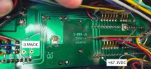
This is nuts. Both drivers installed, outputs in circuit. I'm seeing 2 different voltages on the same trace. Back to +VE reading again when it should be -VE. With F-2508 reg PS and drivers removed, that trace shows open circuit but there's nothing visible.

How on earth is that +65.1VDC getting to the drivers when the regulated PS end of the trace is showing half a volt?!!

Perhaps I should run an external wire between the last pin of F-2508 and the 3rd pin of both left and right drivers?


20260909_100305.jpg
 
Are you saying the two readings in the photo are on the same trace? If so, that's not the case. The photo tells me you have 67V which is correct but the 0.5V reading tells me you're missing negative voltage again.
 
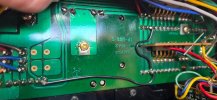
Ran a solid core wire to bypass any trace issues. Now getting equal voltages between reg PS and drivers but STILL +67.1VDC!

DBT pass - drivers and outputs in circuit - driver trimmers fully CCW.

Think I need to focus on F-2508, as the negative 66V rail seems to sporadically switch between +VE and -VE.
I'm going to pull and test each resistor and repalce with metal film.
I'll also upgrade the 2SD381 and 2SD382's to On Semi MJE15034 (8A).


20260909_104825.jpg
Are you saying the two readings in the photo are on the same trace? If so, that's not the case. The photo tells me you have 67V which is correct but 0.5V reading tells m you're missing negative voltage again.
yes, same trace and yes missing the -VE again. See my last post. +67 is not correct, should be -67
 
I would start from scratch, remove both driver boards and the output connector boards F-2510. If you can, also disconnect any load from the 35V regulator.

With just the regulator board in place, see if you can get the negative 65V supply back again and find out why it's flipping positive. Is there a solder bridge or a cracked joint. It seemed to correct itself yesterday when you wiggled the board.
 
I would start from scratch, remove both driver boards and the output connector boards F-2510. If you can, also disconnect any load from the 35V regulator.

With just the regulator board in place, see if you can get the negative 65V supply back again and find out why it's intermittent.
still +VE I'm afraid
 
Back
Top Bottom