• Please note that Audiokarma will be offline briefly for updates early on Monday morning, September 28th.

Sansui Eight help - hum on one channel

Again Tom, dead on! F001 or F002 was blown (not sure which is which). Replaced that and all is well!!! Clear sound on both channels from speakers!

Was able to set DC offset to zero. SM current adjustment has two sets of instructions, one for the "Differential Amplifier" and one for "Main Amp." section. I assume both need to be done?

Diff Amp instruction has one thing that confuses me. VR801 is used to set DC offset to zero. For current adjustment, says to turn VR802 to get 0.5V. Then, with different connections step 7 says to turn VR801 to get zero. Is that correct? If I use VR801, won't that alter the setting from the DC offset?
 
Yes it's very confusing. I am away from my desk, so look up post from AK member trnsfrmr - he has a post dedicated to adjusting the Eight. It makes a big difference. Be careful with the pins, use mini grappers or wait until you can get some. cheers -Tom
 
Thanks guys! Another question that came up in a related thread linked from that one:

https://audiokarma.org/forums/index...er-of-adjustment-for-the-sansui-eight.405735/

I have the early version Eight without a speaker relay. Opinion in that thread by one member was that the F-1334 speaker protector block does not really protect the speakers. I did fry one test speaker in the process of troubleshooting. I see F001-F004 are between the driver boards and the speakers. SM calls for 5A fuses here, but wondering if I should go to a much lower rating such as 1A or 1/2A to better protect the speakers? I'll likely just be using bookshelf speakers with this, and I never play music loud.
 
Last edited:
I'll likely just be using bookshelf speakers with this, and I never play music loud.
F001-F004 are main PSU rail fuses - so they should remain as 5A. However F005 and F006 (according to my schematic), are the speaker fuses, also marked as 5A. I can't believe they need to be 5A so you could try ½ amp fuses (especially now), until you know it is completely stable.

Note also that my schematic does not show a speaker relay, but shows the F-1334 'crowbar' protection circuit, (crummy system), with thyristors to blow those 5A speaker fuses in the event of a fault. (And an odd little circuit F-1202).

If you experience 'nuisance blowing' of those fuses during normal use, you could increase them in stages until this goes away, but make sure that it is just that - a nuisance blow - and not a real fault which will fry your speaker(s). ;)
 
Last edited:
Yes, John, you are right, I got those confused. F005 and F006 are the ones at the back of the unit. I've got 3A in those right now as that is all I had on hand, but will try 1 or 1/2A. I noticed in the other thread trnsfrmr mentions he uses a 1A fuse in line with connection to his test speakers when adjusting amps, so that may be a good idea here for F005/006.
 
Made bias, offset adjustments. Not going to fiddle with this much until I decide what to do with the output transistors. Right now R side has Toshiba 2SC1079 and L side has Sony 2SD88A. Since the two sides are electronically separate, how important is it to have all 4 the same? I've got one more working Toshiba 2SC1079, will see if I can get one more from a guy locally.

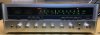
Pots cleaned up easily, and face cosmetics turned out nice. Need 5 of the button labels, but hope to get replacements from an AK member who's had some made. Case needs refinishing, but it's not scratched up, so that should go well.

Sansui Eight front.JPG

Not bad for the $60 I paid for it. :)
 
Made bias, offset adjustments. Not going to fiddle with this much until I decide what to do with the output transistors. Right now R side has Toshiba 2SC1079 and L side has Sony 2SD88A. Since the two sides are electronically separate, how important is it to have all 4 the same? I've got one more working Toshiba 2SC1079, will see if I can get one more from a guy locally.

Pots cleaned up easily, and face cosmetics turned out nice. Need 5 of the button labels, but hope to get replacements from an AK member who's had some made. Case needs refinishing, but it's not scratched up, so that should go well.

View attachment 1540186

Not bad for the $60 I paid for it. :)
Awesome! I wouldn't worry about the differing transistors as long as they are correct for the circuit (they are).
By the way, I'd pull out the crowbar circuit board when you've got this thing all buttoned up and healthy.
 
Can't say that I disagree with ivandezande - these transistors are both slow 1mhz and you probably cant tell a difference between the sides. Sound is largely created by design, not components. However - and this is just me being OCD - I would want them all to be the same, not necessarily today......but eventually. I'd replace them with modern robust and faster MJ21194'g. Then put the others in the parts bin.
 
By the way, I'd pull out the crowbar circuit board when you've got this thing all buttoned up and healthy.

I assume you are talking about the F-1334 board? Or do you mean the F-1202 board? F-1334 is labeled as the speaker protector board in the SM. I'm not really sure what F-1202 does, but both boards are after the driver board and before the speakers in the schematic. Could you clarify what the issue is here and why it should be removed? Can I just use 1A fuses in F005/6 and leave the board where it is?

However - and this is just me being OCD - I would want them all to be the same, not necessarily today......but eventually. I'd replace them with modern robust and faster MJ21194'g. Then put the others in the parts bin.

I tend to do things similarly. I like audio gear to be symmetrical. On the other hand MJ21194g are $7 each, and with shipping they will come to around $9 each. That is why I was leaning toward finding another 2SC1079 locally, if I can. Would there be much difference in sound/performance with the MJ21194g?
 
I assume you are talking about the F-1334 board? Or do you mean the F-1202 board? F-1334 is labeled as the speaker protector board in the SM. I'm not really sure what F-1202 does, but both boards are after the driver board and before the speakers in the schematic. Could you clarify what the issue is here and why it should be removed? Can I just use 1A fuses in F005/6 and leave the board where it is?


I tend to do things similarly. I like audio gear to be symmetrical. On the other hand MJ21194g are $7 each, and with shipping they will come to around $9 each. That is why I was leaning toward finding another 2SC1079 locally, if I can. Would there be much difference in sound/performance with the MJ21194g?
The board right underneath the main filter caps with the two diode half bridges and scr's. It's crowbar protection - not the best to say the least, if it even works.

The MJ21194/5's are crazy better than the 2SC1079's, at least on paper. If this translates to real-world improved performance in your Eight, well, that's up to you.
 
If this translates to real-world improved performance in your Eight, well, that's up to you.
I think it would, in addition those transistors are very tough cookies. (note: normal pairing for PNP/NPN pairs is MJ21193G/94G & MJ21195G/96G).

If you find you need another 2SC1079 - forget it - get some MJ21194G's and be happy. :)
 
Last edited:
New problem. I did find a 2SC1079, so I thought I'd put that in with the other good one I had on the L channel replacing the Sonys. However, when I did that R837 burned up on the L driver board. Should have done this on DBT, but stupidly did not. Pulled the OT on that side, and one of them was shorted. I had tested them before, but the one I had (not the one I picked up) was shorted. That was the one in circuit with R837. F006 was blown also (3A). Replaced R837, F006, and put the Sonys back in. Put on DBT, light goes off then comes back on. So, started going through the whole adjustment procedure following SM. Pulled F001 and F003. Set VR803 to minimum clockwise position on both boards. Set VR802 to minimum counter clockwise position. Set VR801 and VR804 to midpoint. DBT OK.

Started with Bias current adjustment. With DMM connected to F001 contacts I got ~90mA, with no change adjusting L VR803. Put fuse in F001 and put DMM on F003. Here I got ~30mA, but again no change adjusting R VR803. DBT OK in all of these tests.

Thought I'd check current adjustment on drivers. Connected DMM to TP 802 and 801 as directed in SM (p. 15). I started moving up L VR 802 and after about 1/8 turn DBT started to glow and pulse. Tried same procedure on R VR802, same result.

So whatever is wrong is affecting both channels. Wondering where the fault is here? Power supply? Differential pair on both boards? R810 on both boards? Help!
 
Wondering if the 10 times higher bias on the left is the culprit - perhaps the 2 sony outputs could handle it better than when you put in the 2sc1079 - certainly do as John says and get those tracking transistors checked. Another reason for output shorts following replacements could be when you reuse the old Mica's - this is not a death sin, but when you do, then carefully inspect the 50 year old mica insulator AND once the replacement devices are mounted then continuity check the outputs casing (collector) to the chassis (ground) if you hear a beep, the mica likely has a fracture. This could explain the R837 and blown fuse. In fact for good measure do check the replacements casing vs chassis.

Not sure what to make of both channels DC-offset to almost rail. This is a bit weird. If you did not use mini grappers when probing TP801/802, then there is a very high chance that you shorted something around either TP...and since you probed both sides ? It wasn't like that from the beginning and that is the only action I can think of that you applied to both sides.

If you don't already have one then this gadget is invaluable when it comes to testing transistors and will allow you to check differential pairs, tracking transistors etc.....and make sure you put them or their replacements back in ;-)
 
Correction,
Just checked speaker outputs with switch set to A. Both channels show +37.7V.
I didn't properly realise what was being measured here - obviously there is something more serious afoot with nearly 38V on the speaker terminals.
Check your bias tracking transistors TR851/TR852
This check would be a good idea at some point, but you have some other failed semiconductors somewhere in the power amp stage for this to be happening.
  • Work on one channel at a time.
  • Pull out the supply rail fuse of the channel you are not working on.
  • Check the drivers and pre-driver transistors - check their associated resistors.
  • Don't power the unit up with no DBT until both channels are working perfectly bias and DC offset-wise.
Let us know what you find.
 
Last edited:
Well, it didn't take you long to forget this. :(
Check your bias tracking transistors TR851/TR852
OK, checked these. I did not desolder them, but did diode check in place and they tested normal.

Yes, it was really not smart to not use the DBT. I guess I figured since the transistors tested good, it should be ok. Wrong!

Wondering if the 10 times higher bias on the left is the culprit - perhaps the 2 sony outputs could handle it better than when you put in the 2sc1079 - certainly do as John says and get those tracking transistors checked. Another reason for output shorts following replacements could be when you reuse the old Mica's - this is not a death sin, but when you do, then carefully inspect the 50 year old mica insulator AND once the replacement devices are mounted then continuity check the outputs casing (collector) to the chassis (ground) if you hear a beep, the mica likely has a fracture. This could explain the R837 and blown fuse. In fact for good measure do check the replacements casing vs chassis.

Forgot to mention that I did pull TR853-860 and did diode check for shorts. Then put each one back in. I did the test you suggested with the TRs in place and no shorts to ground on any of those TRs.

For clarification, after putting in the 2SC1079s, I was in the process of setting current on the driver on the L channel when R837 started to smoke. I had not worked on the R channel at all. I don't believe I touched something to cause a short. I have some really nice Fluke clamps that are covered in plastic, such that only the teeth are showing. At any rate, I too was mystified why both drivers are displaying the same symptom. It makes me wonder if something has gone bad in the power supply. Could I be getting bad voltage from the PS? Just seems like it has to be something affecting both driver boards equally. I plan to check that voltages from the PS to each board matches what is on the schematic. Visually inspected the PS board. Nothing obviously burned. No bad smell.
 
Back
Top Bottom