• The move to the new server is done. There are some software and database maintenance updates in process. This has us passing the hat around to help out. We appreciate any donations. Seriously, even a dollar helps. The payment page may be found here - https://www.audiokarma.org/support.html

Sansui G-22000 Restoration/Upgrade Thread

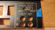
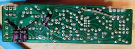
So, here's F2906 that has the side mounted Power Amp-in/Pre-amp out jacks mounted to it. It's got (2) electrolytic caps I'd like to replace, but it's attached to the frame with (4) black plastic pegs that look like they're glued or melted there so I can't just pop them off. Anyone pulled this PCB and how did you reattach?

1747963250440.jpeg

1747963280794.jpeg

1747963327339.jpeg
 
I've used a flat bladed screwdriver to pop them out as far as the back of the "fingers", then used small needle nose pliers or even tweezers on the front side to pop the rivet tab out. You might pick at the glue first to loosen it up.
 
So, here's F2906 that has the side mounted Power Amp-in/Pre-amp out jacks mounted to it. It's got (2) electrolytic caps I'd like to replace, but it's attached to the frame with (4) black plastic pegs that look like they're glued or melted there so I can't just pop them off. Anyone pulled this PCB and how did you reattach?

View attachment 3509577

View attachment 3509578

View attachment 3509579
Push the centre part of those back with a pick or very small screwdriver.
Also, those caps are nothing to do with the normal operation of the G22K when you are using the 22K power-amp. Those caps are for if you want to use another power-amp which requires a cap coupled input. You would select on that Connected/Separated switch "cap coupled" for that function.
A couple of other things about that board, see the green blob? That is possibly one of the most unreliable relays on the planet, so if you are planning on using the outputs on that panel or just want everything to work, replace that relay. You may not find a drop in replacement but you can mount one upside down and wire it "dead bug" style.
Also, pull the switch, dismantle and clean properly. Its the most common source of audio drop-outs with these amps.
 
You might pick at the glue first to loosen it up.
Those black plastic things are called 'snap rivets', they have varnish on them, I have found if you put some flux cleaner on them first this helps with the removal process as described by our esteemed AK guru's. (if you damage them, replacements are available from Mouser or Digikey).
 
Thanks for all the intel on those snap rivets on F2906. Turned out the top 2 in the photo above had what I believe is referred to as Glyptal. With a little extra effort, I was able to get them to pop out undamaged. The lower 2 had none at all and popped right out. Got the 2 BP caps swapped out and gave the switch a few good shots of deoxit and worked it. Hadn't had any issues with it to date, so hopefully I'm good for a few more years. Don't plan to use this option, so I'll leave the relay in place. Just waiting for a couple of caps to come in for the tuner board and I'll be done with this half of the unit.

1748299085200.jpeg
 
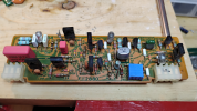
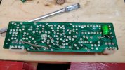
Wrapped up the tuner board and fired the thing up again. Went through the audio section alignments and flat amp and driver circuit boards dialed in perfect, but "both" EQ amp PCBs are stuck on 0 VDC- won't adjust. They did before I worked the cards. Replaced the 3 caps on the back and replaced the single turn 100-ohm single turn pot with a multi turn.
 

Attachments

  • Tuner.jpg
    Tuner.jpg
    113.7 KB · Views: 8
  • EQ Amp.jpg
    EQ Amp.jpg
    74.9 KB · Views: 8
  • IMG_20250522_211519520.jpg
    IMG_20250522_211519520.jpg
    75.9 KB · Views: 8
  • IMG_20250522_211154090.jpg
    IMG_20250522_211154090.jpg
    104.4 KB · Views: 8
Last edited:
So, apparently you've got to find the sweet spot on the pot and then you can adjust. However, initially (before I worked the PCBs) it was really hard to get the EQ PCB to adjust to 0 volts as the slightest move to the pot made a drastic change. Even with a multi turn it's touchy. I can get it to 0 VDC, but very hard to get the reading to settle within range- it wants to drift, like 50 mV- even after 20 mins of warm up. Is that normal? Poth PCBs do the same.
 
So, been fooling around with the adjustment quite a few times now. I can get it close to zero, but it continually jumps around. My best setting keeps it within + or - 30 mVDC. It will swing back and forth above and below zero, but kinda depends on the set point as far as how far negative or positive it goes. When I first turn on the unit, those readings are in the -500+ mVDC range, but eventually gets to where they're in that +/- 30mV range- within a minute or 2. One card does take a bit longer to come down than the other. Does that sound typical to others that have made that adjustment or is yours more stable? Not sure I have an issue since both cards act the same.
 
Last edited:
So, been fooling around with the adjustment quite a few times now. I can get it close to zero, but it continually jumps around. My best setting keeps it within + or - 30 mVDC. It will swing back and forth above and below zero, but kinda depends on the set point as far as how far negative or positive it goes. When I first turn on the unit, those readings are in the -500+ mVDC range, but eventually gets to where they're in that +/- 30mV range- within a minute or 2. One card does take a bit longer to come down than the other. Does that sound typical to others that have made that adjustment or is yours more stable? Not sure I have an issue since both cards act the same.
Yeah the DC offset does drift around a bit. I have noticed as those JFET differential pairs age it gets worse....Just get it the best you can and see how things progress...
 
Thanks for the confirmation. Before wrapping this up I went back and made the "mattsd" recommended cap changes to those boards. Had to use a .018 uf for C12 since a .016 wasn't available. Now time to put this thing back together.
 

Attachments

  • 1748948855150.png
    1748948855150.png
    747.7 KB · Views: 7
  • IMG_20250602_183306427.jpg
    IMG_20250602_183306427.jpg
    94.1 KB · Views: 7
Had to use a .018 uf for C12 since a .016 wasn't available.
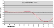
That's going to alter the RIAA compensation a bit, how much? - I wonder if @Leestereo would be kind enough to help with that? The schematic says C12=0.016µF + C11=510pF, these are in parallel. So the stock capacitor combination is 16,510pF, and you now have C12=0.018µF +C11=510pF, =18,510pF, the difference is 2,000pF that's quite a big difference. I understand the component availability issues, they are a total pain, but perhaps a different choice of replacement would be wise?

I just checked Mouser and Digikey - you were right, no joy, perhaps wait until we know how much effect the extra 2,000pF will make - then think about solutions. (perhaps a two capacitor combination adding up to 0.016µF - it seems like the paralleled 510pF (C11), should be retained in view of the excellence of its dielectric.

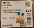
A couple of pairs of these should do it:

Update - no idea how I missed these - they are indeed, as you say below "a better choice" - exactly what is needed.
 
Last edited:
That's going to alter the RIAA compensation a bit, how much? - I wonder if @Leestereo would be kind enough to help with that? The schematic says C12=0.016µF + C11=510pF, these are in parallel. So the stock capacitor combination is 16,510pF, and you now have C12=0.018µF +C11=510pF, =18,510pF, the difference is 2,000pF that's quite a big difference. I understand the component availability issues, they are a total pain, but perhaps a different choice of replacement would be wise?

I just checked Mouser and Digikey - you were right, no joy, perhaps wait until we know how much effect the extra 2,000pF will make - then think about solutions. (perhaps a two capacitor combination adding up to 0.016µF - it seems like the paralleled 510pF (C11), should be retained in view of the excellence of its dielectric.

A couple of pairs of these should do it:
Wow, the capacitance was so small i didn't think it would make any difference, but then I'm not real sharp on circuit theory. Posted the alteration so someone might chime in incase it might be an issue. If it is, how would it reveal itself in operation? I've had it up and went through the amp adjustments one last time. Everything looks good except the aforementioned eq adjustment that wonders a bit. I've only listened to FM so far with headphones and it sounds fine. Was gona check the power meter adjustment, jam some speakers, make sure all the inputs/outputs still work and then close it up.
 
It might present itself as a weird tonal balance, but only when playing vinyl records, that's the only thing it would affect.
 
Thank you Ben, you are an absolute *Star* :thumbsup::bowdown:

We all learnt something thanks to you. :thumbsup:
 
Last edited:
That's going to alter the RIAA compensation a bit, how much? - I wonder if @Leestereo would be kind enough to help with that? The schematic says C12=0.016µF + C11=510pF, these are in parallel. So the stock capacitor combination is 16,510pF, and you now have C12=0.018µF +C11=510pF, =18,510pF, the difference is 2,000pF that's quite a big difference. I understand the component availability issues, they are a total pain, but perhaps a different choice of replacement would be wise?

I just checked Mouser and Digikey - you were right, no joy, perhaps wait until we know how much effect the extra 2,000pF will make - then think about solutions. (perhaps a two capacitor combination adding up to 0.016µF - it seems like the paralleled 510pF (C11), should be retained in view of the excellence of its dielectric.

A couple of pairs of these should do it:

Update - no idea how I missed these - they are indeed, as you say below "a better choice" - exactly what is needed.
To your update- I don't know how I missed it either. Even worse, I actually ordered it along with all the other caps for that board and then forgot I ordered it- DOH! Long story to explain how that happened, but glad I advertised the .018 uf install or I'd be none the wiser. So glad I have access to this site and thankful for all those who take the time to double check my work.
 
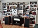
Installed the .016uf cap, tweaked the power meter adjustment just a tad and closed it up. Back in its rightful spot and all appears to be working fine. Thank you to all you participated, helped and followed along. Much appreciated!
 

Attachments

  • IMG_20240201_155723140_HDR.jpg
    IMG_20240201_155723140_HDR.jpg
    129.6 KB · Views: 11
  • IMG_20240201_155734328_HDR.jpg
    IMG_20240201_155734328_HDR.jpg
    160.8 KB · Views: 11
Back
Top Bottom