

You are using an out of date browser. It may not display this or other websites correctly.
You should upgrade or use an alternative browser.
You should upgrade or use an alternative browser.
Sansui G-22000 Restoration/Upgrade Thread
- Thread starter mattsd
- Start date
-
- Tags
- g-22000 recap restoration sansui

No, the typical recommendation I see now is to use metal film types of like wattage as replacements. The fusible types are notorious for drifting in value, and since they often play a critical role in the biasing circuit, their failure often results in blown channels by creating instability.

Matt03221
Active Member
Ok, that took some figuring. Looks like there are 3 fusible resistors on each of those power supply boards- R8 (47ohm), R16 (47ohm) and R44 (4.7ohm). Legend on the schematic uses a box with a slash through it to indicate a fusing resistor. Parts list IDs them with (F.R.). All that a waste of time as "mattsd" already identified those in his restoration effort earlier in this thread. DOH! Should've checked that first. Looks like I need to order some metal film replacements- damn!

kevzep
Its all about the Music
They are small chalky beige colour, do not confuse them with the larger bluish resistors which are not fusible. They are just flameproof.Thanks for the heads-up! Now that you mention that it seems I recall reading that somewhere. How would i recognize those or how are the ID'd in the manual? They're not jumping out at me. Don't know that I've ever seen a fusible resistor .
On the driver board they'd be R33 and R34, 150Ω, some are fusible some are not....If they are shiny and look like the others then they are not fusible.
If they are beige and chalky looking, measure them and they'd for sure be way higher than they should be...
Then for the power supply boards just have a look around, they are always going to be on some regulated supply rails, always low values....
kevzep
Its all about the Music
I use metal oxide as they behave like a fuse resistor, you can use metal film, up to you, most people use metal film....Ok, that took some figuring. Looks like there are 3 fusible resistors on each of those power supply boards- R8 (47ohm), R16 (47ohm) and R44 (4.7ohm). Legend on the schematic uses a box with a slash through it to indicate a fusing resistor. Parts list IDs them with (F.R.). All that a waste of time as "mattsd" already identified those in his restoration effort earlier in this thread. DOH! Should've checked that first. Looks like I need to order some metal film replacements- damn!
Matt03221
Active Member
Why do you mention R33 and R34 on the driver boards? I see them on the schematic as well as mattsd's pics of the board, but they look like carbon resistors and are not identified as fusible in the manual. Is there some other issues with those resistors?They are small chalky beige colour, do not confuse them with the larger bluish resistors which are not fusible. They are just flameproof.
On the driver board they'd be R33 and R34, 150Ω, some are fusible some are not....If they are shiny and look like the others then they are not fusible.
If they are beige and chalky looking, measure them and they'd for sure be way higher than they should be...
Then for the power supply boards just have a look around, they are always going to be on some regulated supply rails, always low values....

Please can you take a picture of your driver boards and post it here? We'll be able to advise about those resistors if we can see them, or maybe you have a picture that is the same visually as yours that you can point us to?Why do you mention R33 and R34 on the driver boards? I see them on the schematic as well as mattsd's pics of the board, but they look like carbon resistors and are not identified as fusible in the manual. Is there some other issues with those resistors?

DB-7
Super Member
@Matt03221On the driver board they'd be R33 and R34, 150Ω, some are fusible some are not....
Unfortunately that's too dark to see what we want to see, can you take a much better illuminated - and larger one, of your driver board?For convenience I grabbed mattsd's pic of his unmodified driver amp board from page 2 of this thread. You can see R33/34 between each of the 2 big caps and the center pot.
Last edited:
Matt03221
Active Member
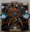
That's something I don't get about this site. Some folks can post really big clear pics, but when I try to do it, I always get rejected for the file being too big when it's not. Anyway, look at page-2 two of this thread about halfway down the page mattsd has very clear pics of the driver boards. you can easily see R33/34 on the middle of the board. It looks like this...
Attachments
Last edited:
I hear you on that one - not sure why that is.That's something I don't get about this site. Some folks can post really big clear pics, but when I try to do it, I always get rejected for the file being too big when it's not.
Post #33 contains some in focus, well illuminated pictures but those resistors are either hiding behind driver transistors or have been removed!
Anyway, why are we discussing this? - is it just to decide whether or not to replace them? - just replace them and have done with it!

What little I could see of them makes me think they ARE fusibles anyway - 'dark green' is another variant - so I would advise replacing them without further thought.
kevzep
Its all about the Music
Thats what I am saying, sometimes, they are fuse resistors, sometimes they are not. Sounds like yours are not.... So you can just leave those..Why do you mention R33 and R34 on the driver boards? I see them on the schematic as well as mattsd's pics of the board, but they look like carbon resistors and are not identified as fusible in the manual. Is there some other issues with those resistors?

Matt03221
Active Member
So, got my resistors in and wrapped up the power amp section. My inexperience is coming out now. Did a test with my dim bulb tester. Unit came up, got a green light after a few seconds and it's playing FM fine through the headphones, but a little concerned about the brightness of my 200 watt bulb there on the DB tester behind the PA section. It's not quite as bright as it looks in the pic, but much brighter than other receivers. The bulb doesn't have the aura you see in the pic, but the filament is a good solid orange. I've got a Technics SA-800 and an SA-818 here in the same room. When I put them on the tester, I barely get the filament to glow once they settle in. When I turn on the 22000 it starts out bright and goes down quickly, but I'm feeling like that's a bit too much. Have I got an issue? Should I pull F702 and check the Amp reading across that? Power consumption rating from the manual is 950 Watts / 1,100 VA. What should I read there?

It's a big powerful receiver, built with an order of magnitude more Oomph than other receivers so you can expect it to draw more current, and therefore exhibit a somewhat brighter bulb than other lesser models.but much brighter than other receivers.
No, I don't think so, BUT before you remove the DBT check that you can adjust Bias current. Providing it can actually be adjusted and does not show signs of instability (like sudden brightening of the bulb), after testing the adjustment turn down the bias to say half of what it should be. Power off and remove the DBT for a full mains test. Power on and monitor the bias immediately and don't run a signal through the amp until you have the bias adjusted correctly, after allowing some warm up time - monitoring bias all the time. It will drift a bit and this is normal, but it shouldn't go up and keep going - that's a danger sign.Have I got an issue?
Matt03221
Active Member
I Love this site. Thanks for the intel and reassurance!! Leaving it on the DB tester I checked DC on the speaker terminals and the bias current in accordance with the service manual adjustments for the power amp section. Readings were close, but went ahead and tried to dial them in. Pots for 0VDC at the speaker terminals were super sensitive, jus barley turning the right channel pot and it would jump as high as 500 mv. However, with some patients I got both channels within 3mv of "0"- definitely will replace those pots though. Got the bias current dialed in easy. No fluctuations in the DB intensity while doing all that and it took a good 20-30 mins. The unit seemed fine through all that and the safety circuit never kicked in, so hopefully I'm ok. We'll pull it off the tester and check it out like you recommended.It's a big powerful receiver, built with an order of magnitude more Oomph than other receivers so you can expect it to draw more current, and therefore exhibit a somewhat brighter bulb than other lesser models.
No, I don't think so, BUT before you remove the DBT check that you can adjust Bias current. Providing it can actually be adjusted and does not show signs of instability (like sudden brightening of the bulb), after testing the adjustment turn down the bias to say half of what it should be. Power off and remove the DBT for a full mains test. Power on and monitor the bias immediately and don't run a signal through the amp until you have the bias adjusted correctly, after allowing some warm up time - monitoring bias all the time. It will drift a bit and this is normal, but it shouldn't go up and keep going - that's a danger sign.

kevzep
Its all about the Music
The idle current will make the lamp glow slightly, completely normal for an amplifier of this magnitude.So, got my resistors in and wrapped up the power amp section. My inexperience is coming out now. Did a test with my dim bulb tester. Unit came up, got a green light after a few seconds and it's playing FM fine through the headphones, but a little concerned about the brightness of my 200 watt bulb there on the DB tester behind the PA section. It's not quite as bright as it looks in the pic, but much brighter than other receivers. The bulb doesn't have the aura you see in the pic, but the filament is a good solid orange. I've got a Technics SA-800 and an SA-818 here in the same room. When I put them on the tester, I barely get the filament to glow once they settle in. When I turn on the 22000 it starts out bright and goes down quickly, but I'm feeling like that's a bit too much. Have I got an issue? Should I pull F702 and check the Amp reading across that? Power consumption rating from the manual is 950 Watts / 1,100 VA. What should I read there?
View attachment 3488985View attachment 3488998
Also, remember the DBT is a GO/NO GO test, once its passed get it on the mains, then and only then set the bias.
You failed to follow the instructions from @Hyperion You turn the BIAS current down before taking it off the DBT. Then when on mains (Off the DBT), do the BIAS setting routine from a point of lower current, then work your way up.I Love this site. Thanks for the intel and reassurance!! Leaving it on the DB tester I checked DC on the speaker terminals and the bias current in accordance with the service manual adjustments for the power amp section. Readings were close, but went ahead and tried to dial them in. Pots for 0VDC at the speaker terminals were super sensitive, jus barley turning the right channel pot and it would jump as high as 500 mv. However, with some patients I got both channels within 3mv of "0"- definitely will replace those pots though. Got the bias current dialed in easy. No fluctuations in the DB intensity while doing all that and it took a good 20-30 mins. The unit seemed fine through all that and the safety circuit never kicked in, so hopefully I'm ok. We'll pull it off the tester and check it out like you recommended.