

You are using an out of date browser. It may not display this or other websites correctly.
You should upgrade or use an alternative browser.
You should upgrade or use an alternative browser.
Sansui G-22000 Restoration/Upgrade Thread
- Thread starter mattsd
- Start date
-
- Tags
- g-22000 recap restoration sansui

Matt03221
Active Member
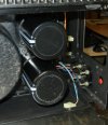
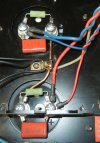
First, nice work there. Set up looks the same as mine, so definitely safe to say the manual either has the polarity wrong, the capacitor ID numbers reversed or I'm reading it wrong. Either way, time to get it done. Appreciate everyone's time and comments. I may have more crazy questions as I work through this thing. It will be a long process though as I was lazy and ordered a cap kit off ebay. Never seem to get one that's been properly vetted, so constantly finding they missed stuff.

Thank you! There were production changes I bet so maybe why the cap kit wasn't quite right.First, nice work there. Set up looks the same as mine, so definitely safe to say the manual either has the polarity wrong, the capacitor ID numbers reversed or I'm reading it wrong. Either way, time to get it done. Appreciate everyone's time and comments. I may have more crazy questions as I work through this thing. It will be a long process though as I was lazy and ordered a cap kit off ebay. Never seem to get one that's been properly vetted, so constantly finding they missed stuff.

kevzep
Its all about the Music
I've worked on a number of these amps, there is nothing odd about them, it's very straight forward and typical of a complementary output stage. You don't need the wiring diagram to confuse you.Can't check voltages now as I had to pull the thing half apart just to reveal the wiring on those caps. My plan is to wire the new caps to match the current config of the unit and not the schematic. However, I was hoping someone who's been through the process on the 22000 would chime in and confirm they noticed the same discrepancy- I'd feel better.
You will have a +'ve supply rail and a -'ve supply rail.
You will see the -'ve rail connects to the 2SA (PNP) output transistors, and the +'ve rail connects to the 2SC (NPN) output transistors.
That will tell you what you need to know about the capacitors polarity. Just be aware that the POSITIVE terminal of the cap for the -'ve supply rail will go to ground.
You can see this in the pics of the last post, but ALWAYS verify you have it right otherwise it is a big messy and smelly explosion!!
Let us know how you get on...

The Fuxtor
Addicted Member
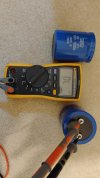
Odd?? The meter is in capacitance mode . What's it do when you measure ohms?
Matt03221
Active Member
It stays at zero thru all the ranges. Weird, like maybe it's just to big for the meter.That really isn't zero.
It is out of limit.
Try changing the setting on the meter.
Matt03221
Active Member
If i check it with my analogy meter, it acts like a cap should.Odd?? The meter is in capacitance mode . What's it do when you measure ohms?
That's exactly why!It stays at zero thru all the ranges. Weird, like maybe it's just to big for the meter.
This is why I use the Peak capacitor tester to check capacitance and ESR. The bad part is, below 1uf it won't read. That's where the Fluke comes in.It stays at zero thru all the ranges. Weird, like maybe it's just to big for the meter.
Yup, all the greats do it this way!!This is why I use the Peak capacitor tester to check capacitance and ESR. The bad part is, below 1uf it won't read. That's where the Fluke comes in.

DB-7
Super Member
Good to know. I have same meter. Same unread manual.I should've checked the manual first. Fluke 117 Cap range from 1nF to 9999uF. In the meantime, waiting for a few parts to come in before pressing with the project.

Beautiful work though!Here's my swag at the filter caps. Not the best but what an F-ing pain in the tale- and that's just first two.
Matt03221
Active Member
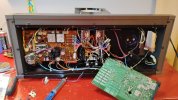
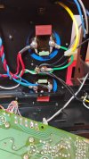
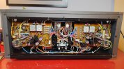
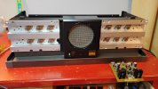
Left channel filter caps done. L/R power supplies and driver amp PSBs recapped. All transistors with a heat sink got new compound. I bought this thing used around 2003, but this is the first time I've really spent any time inside. Looks completely untouched and in pretty good shape. No heat stress on any of the PCBs. Time to fire it up on the DB tester and if there no issues, I'll press with checking the adjustments before moving on to the preamp/tuner section- not looking forward to that.
Attachments

kevzep
Its all about the Music
Dont forget to replace the few fusible resistors there are in some G22000, there are two on each driver board, and there are a couple in the regulated supplies.Left channel filter caps done. L/R power supplies and driver amp PSBs recapped. All transistors with a heat sink got new compound. I bought this thing used around 2003, but this is the first time I've really spent any time inside. Looks completely untouched and in pretty good shape. No heat stress on any of the PCBs. Time to fire it up on the DB tester and if there no issues, I'll press with checking the adjustments before moving on to the preamp/tuner section- not looking forward to that.
Some have them, some don't, but worth checking, mine had them and of course they had all drifted way off spec.
Matt03221
Active Member
Thanks for the heads-up! Now that you mention that it seems I recall reading that somewhere. How would i recognize those or how are the ID'd in the manual? They're not jumping out at me. Don't know that I've ever seen a fusible resistor .Dont forget to replace the few fusible resistors there are in some G22000, there are two on each driver board, and there are a couple in the regulated supplies.
Some have them, some don't, but worth checking, mine had them and of course they had all drifted way off spec.

They are often low resistance values (single or double digit ohms with no multiplier) and usually the bodies are kind of a chalky greyish color, which sets them apart from the brown and tan carbon resistors and the blue metal film types. The schematic and parts list will be typically list them as "fusible resistors".