• The move to the new server is done. There are some software and database maintenance updates in process. This has us passing the hat around to help out. We appreciate any donations. Seriously, even a dollar helps. The payment page may be found here - https://www.audiokarma.org/support.html

Sansui Turntable - Particularly XR-Q11

Still working on it, not dead yet! In the meantime, wife has kicked me off the kitchen table so I have been reinventing the workshop. Pictures soon.

Also in the meantime, our first grandson was born! Pictures soon.

Also in the meantime, somebody dumped a Husky at the end of road in the country. It bit my wife then continued to hang around in the tree-line in really cold, snowy weather. We spent the last week trying to trap it. Today success! Pictures soon.

So, in the soon-to-be meantime, back to de-soldering and soldering...Pictures soon. :rflmao:

The good news, I haven't given up yet.
 
A grandkid (congrats) and a dog in the same week? Huskies are neat dogs, I had one years ago. But they are drama queens, and stubborn as alll hell. If you plan to keep it, be aware of the quirks or the breed. And when they shed...

At any rate, I'll be looking for the exciting conclusion to this one.
 
As promised, the dog that took several days to capture:
upload_2023-2-1_11-34-57.png

And the new workshop setup, adorned with a picture of the grandson:
upload_2023-2-1_11-37-25.png
@Sansuiman, so dog actually started this whole adventure by being dumped and biting my wife. We have 3 Vizslas, talk about quirky. No, the rabies shots were astronomical $$$, no home here, currently at the Humane Society. I hope it has a positive outcome. Enough about that, back to work...

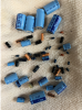
I tried the Hakko de-soldering and wow, one component and I can already recommend it. It is an FR301-03/P:
upload_2023-2-1_11-43-31.png

OK pricy, but how did I do electronics all these years without it!

First component, that trim pot...came right out. And, one leg was indeed broken. :-) the Fun begins.
 
upload_2023-2-2_20-42-55.png

Well, this is kind of an anticlimactic finish. I did the recap. Everything works first time, no adjustment needed. Track select: Perfect!

I'll see if I can share some videos tomorrow. I think I will also run through the oscilloscope traces just to have a nice baseline. Still need to add a cartridge, check out the muting, all that stuff. Anyway, there it is, the XR-Q11, top-of-the-top of the top-of-the-line of Sansui turntables, at least as far as the most expensive turntable that Sansui sold. Hope you enjoyed my ramblings...
 
Bravo. Consider me suitably impressed at the effort and thoroughness of documenting this proiject through to it's completion.. Now we know it can be done, and that despite some weaknesses in the obscenely complex design, it can work perfectly. The latter point is particularly significant because these tables (to include the XR-Q7 and 9 as well) have gotten a very had rap for years owing to their obviously age-related failures. You were the first to prove "in the clear" that they can be refreshed to full original function.

Clearly Sansui stretched a bit within the technological constraints of the period to do these, and at a time when they were starting to slip financially as a company (circa 1980) yet they still had the engineering expertise and determination to see it through and deliver a masterpiece.

It is worth pointing out that prior to this, the BSR Accutrac models were the major players in the programmable playback turntable space. Having owned a couple of them many years ago - and being quite disappointed in their quality - the XR-Q11 represents what I consider the definitive statement in an actual high quality turntable to feature track programmability.

Regrettably, it was the last such effort since Sansui's turntable offerings went downhill rather quickly after the XP-99, which was the follow up to the XR-Q lineup. A couple of "plastic fantastic" drawer load models with programmability came later still, but weren't of anywhere near the quality that had been established by Sansui previously. CD then pretty well killed off the entire product category by 1987, until the vinyl resurgence of more recent years.
 
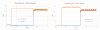
Well, maybe not done. Here's the power supply, before and after recap:
upload_2023-2-5_17-58-30.png

Still dipping negative for about 1.5 seconds during startup. I would really like to track this down but it looks like a fundamental design issue, probably some type of interaction of the upstream or downstream components. I disconnected the downstream components from the power supply. Here's what I got:
upload_2023-2-5_18-7-2.png

Sorry, the tops clipped a little.

It looks maybe ok, the short cycle is ~120Hz, consistent with the way the rectifier will double the line frequency of 60Hz. Seems like the capacitor should smooth this out a little more but, well, maybe not. But where is the slower ~10Hz cycle from?

Still, no sign of where the voltage surge in the +14V line comes in to force the output negative. So it must be some downstream component. Well, I give up. The fact that Sansui completely redesigned the power supply on the very similar FR-D55 suggest they knew something was wrong.

Important in my book is that every XR-Q11 should eventually fail in exactly the same way. Here the fix. The +14V line has plenty of voltage in excess to supply the +5V regulator. So the voltage drop from a diode (0.2 to 0.6V) on the +14V feed line will not hurt. And that should clamp the voltage to >0V and save the tantalum capacitors.
 
upload_2023-2-5_18-28-31.png

I will see if I can find a diode in the "repurpose bin" that can handle a minimum of 25V and a current matching the max pulse current for Q34, a 2SD471, rated at 8A.

I'll let you know how it goes.
 
Last edited:
Correction, the rectifiers in the power supply, the RB152's are rated at 1.5A. I found some 1N5401's (100V 3A Vf = 1V) should work...
 
OK it wasn't a mistake, it was a happy accident (thanks Bob Ross!).

I installed the diode backward and had a great +19V on the supply side and -0.5V on the regulator side! So the negative voltage is something feeding back on the +5V supply line. First off, the diode, therefore, is not going to work because the negative voltage is not coming from the supply side.

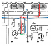
2nd learning, I think the Q32, Q33 and Q33 are there as a soft-start or delay for the voltage to the +5V regulator. You know, this whole mess that feeds the +5V regulator:
upload_2023-2-5_20-29-10.png

I was never really sure what it did. But now I think it's a soft-start. And I think the design error is that the -5V line starts up immediately while the +5V line soft-starts up over 1.5 secs. During that time, something is reversed biased and draws the line low to -0.5V like maybe even a simple route like down through R132 and back up R135 (the resistors around Q28). Well, it's a theory anyway...got to go pour over the schematic, maybe make some tests.

Got to tell you though, this has been a really interesting winter project. Still shakin' that bush here, boss...
 
The above circuit is a delay start for the +5V line. Q34 is like a switch turning the power (+14V) to the +5V regulator on and off. Q33 is an inverter. When Q33 is on, the base of Q33 is pulled down, turning Q34 off. Q32 is the interesting part of the circuit. R145 and C46 take time to charge at startup. Dz8 is a zener diode that does not let the base of Q32 see any voltage until it gets above a certain point. So the RC circuit charges up. The voltage eventually gets above the zener breakdown voltage and activates the base of Q32, turning Q32 on. That turns Q33 (the inverter) off. That turns Q34 on and provides +14V to the regulator, which can now provide power to the +5V supply line.

Why the delay start? No idea. Something must have been malfunctioning like the microprocessor while trying to startup at the same time as everything else.

The unfortunate part, the Sansui engineers did not delay-start the -5V supply. So there is about 1.5 seconds when the -5V supply is up and the +5V supply is down.
 
Unfortunately, the -5V supply is not isolated from the +5V supply:
upload_2023-2-6_6-46-50.png

So there it is. During startup, +5V is delayed, -5V feeds back through a couple of resistors to bias the +5V line low. That reverse biases the tantalum capacitors and after enough on-off cycles, they fail.

I didn't actually make any measurements (yet) but I did set up the circuit in LTspice, at least the important parts, and sure enough, it duplicates the -0.4V o nthe +5V line during startup.
 
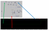
upload_2023-2-6_6-57-39.png
Here's the circuit simulation, you can see the +14V line that supplies the +5V regulator (green) dips below zero until the delay-start circuit let's +14V supply line (blue) provide voltage through Q34. That's because the -14V supply line (red) is already providing power to the -5V regulator.

OK this is not an entirely accurate circuit, the -14V supply goes through the -5V regulator first, but you get the idea. But the simulation verifies the function of the delay-start circuit and the feedback of the negative supply to the positive supply line during that delay. And the delay of 1-2 seconds is about what we see in real life and the negative dip is a couple hundred millivolts, again within reason of what we are seeing in the actual circuit.

I'm open to suggestions about what to do...I would love to use a diode somewhere to prevent this but I think the voltage drop would mess up the biasing on Q28. I would probably need to change out the resistors.

And I'm not convinced that there aren't one or two more places that this same thing happens elsewhere in the schematic.
 
upload_2023-2-6_7-50-38.png

At least one more path from -5V to +5V (red) and a couple of paths that will leak if reversed biased (green). I think the voltage drop across the diodes is what is setting the level on the negative voltage swing during startup. Anyway, this does not include any paths on the motor control board.

Point is, too many possible interactions and/or paths to really control this easily by isolating things on a path by path basis. Which is why Sansui completely redesigned the power supply on the FR-D55.

I guess I'm really thinking at the point of living with this and hoping that the 1.5 seconds of -0.5V reverse bias on the tantalums will take a while to degrade the caps.
 
Hi mootej
Fantastic thread!
Tonight I found one of these on fb for 600 DKK (90 USD), in good cosmetic condition and seemingly in working order, though the track selection may be defective.
I tend to buy turntables by weight and at less than 4 USD a pound it seemed a bargain, so this was a case of buy first and figure out the repair later, though I did check that a service manual was available.
Obviously I had no idea what I was getting into, and I had actually seen the whiny video but didn’t connect the dots and so might have become disencouraged, but finding this thread saves my bacon.
Rather a marvelous piece of kit, that I now look forward to working on.
I am picking it up Thursday.
Regards Jens
 
Last edited:
Hi mootej
Fantastic thread!
Tonight I found one of these on fb for 600 DKK (90 USD), in good cosmetic condition and seemingly in working order, though the track selection may be defective.
I tend to buy turntables by weight and at less than 4 USD a pound it seemed a bargain, so this was a case of buy first and figure out the repair later, though I did check that a service manual was available.
Obviously I had no idea what I was getting into, and I had actually seen the whiny video but didn’t connect the dots and so might have become disencouraged, but finding this thread saves my bacon.
Rather a marvelous piece of kit, that I now look forward to working on.
I am picking it up Thursday.
Regards Jens
I am so glad you enjoy this!!! It was a fun project. Got to admit, I need to push for the last couple of things, polish the actual dust cover, get a good cartridge, get or make the legs and the motor cover. Summer got here, so it will wait till cold weather. But please, Jens, update us on your progress. I would love to follow.

And it would still be slick to dump the code from the CPU, if only for posterity. But that's a whole other project!
 
Thanks mootej,
I have no idea when I will get around to working on this project, as I have had a bit of a kid in a candy store episode, buying projects faster than I can handle.
This is a bit more complicated than the DUAL’s I have been working on, as they roughly have the electronic complexity of a light switch.
I definitely will report back, and my present plan is to fix all mechanical issues, and then do a full recap. For any electronic issues this thread is the gold standard.
I will report the condition of the turntable as soon as possible, and add any additional information to this thread.
Thanks to you, this will probably be a manageable project.
Best regards Jens
 
Last edited:
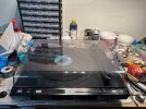
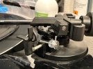
Here it is :)
Some movement on the tonearm, but no set down, and a bit of jitter on 33 rpm, the latter is probably a minor issue.
It seems able to detect the pauses between tracks.
What thickness is the rubber mat? Mine is missing and replaced with a slip mat :-(
Beautiful pice of kit, but it is the first time I consider polishing a plinth.
 

Attachments

  • IMG_6131.jpeg
    IMG_6131.jpeg
    130.8 KB · Views: 20
  • IMG_6127.jpeg
    IMG_6127.jpeg
    123.2 KB · Views: 20
  • IMG_6129.jpeg
    IMG_6129.jpeg
    111.3 KB · Views: 20
Here it is :)
Some movement on the tonearm, but no set down, and a bit of jitter on 33 rpm, the latter is probably a minor issue.
It seems able to detect the pauses between tracks.
What thickness is the rubber mat? Mine is missing and replaced with a slip mat :-(
Beautiful pice of kit, but it is the first time I consider polishing a plinth.
OK so where are we now?
 
OK so where are we now?
Sidetracked:oops:
After accumulating 46 turntables and 20 odd other pieces of gear that all need repairing, I have stopped hunting/hoarding and started on fixing and reducing the inventory. I think I have a couple of years of entertainment sitting around.
Am also learning a lot by repairing the less complicated stuff, before I tackle the bigger jobs.
I will get there but it may take a while ( turntable count just dipped below 40)

Edit: well now you have given me the itch, so I will finish a couple of simple turntables that are not going to stay in the collection and free up some space, and then tackle this and the Beolab Penta crossoveres and amplifiers that I plan to give to my son for his birthday at the end of July :angel:
Do you have a measurement for the mat thickness?
 
Last edited:
Back
Top Bottom